Girder Point Load Generator Tool |
  
|
Girder Point Load Generator Tool |
|
When designing a girder, users will often find it necessary to account for the reactions exerted by each of the infill beams that the girder supports. While this task is sometimes done using an equivalent line load approximation for the sake of simplicity, ENERCALC for Revit provides the user with a variety of options for applying these reactions to ensure fast and accurate design of girders.
Option 1: Non-Hosted Point Loads
It’s always possible to explicitly apply point loads to a girder manually using the native Revit interface (via the Revit Analyze ribbon tab). Unfortunately, per native constraints in Revit, loads hosted to the girder itself (Analyze > Loads > Hosted Point Loads) would only be permitted to be defined at the girder’s two end joints. Therefore hosting loads to the girder itself is not helpful for girder design.
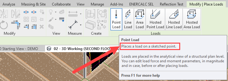
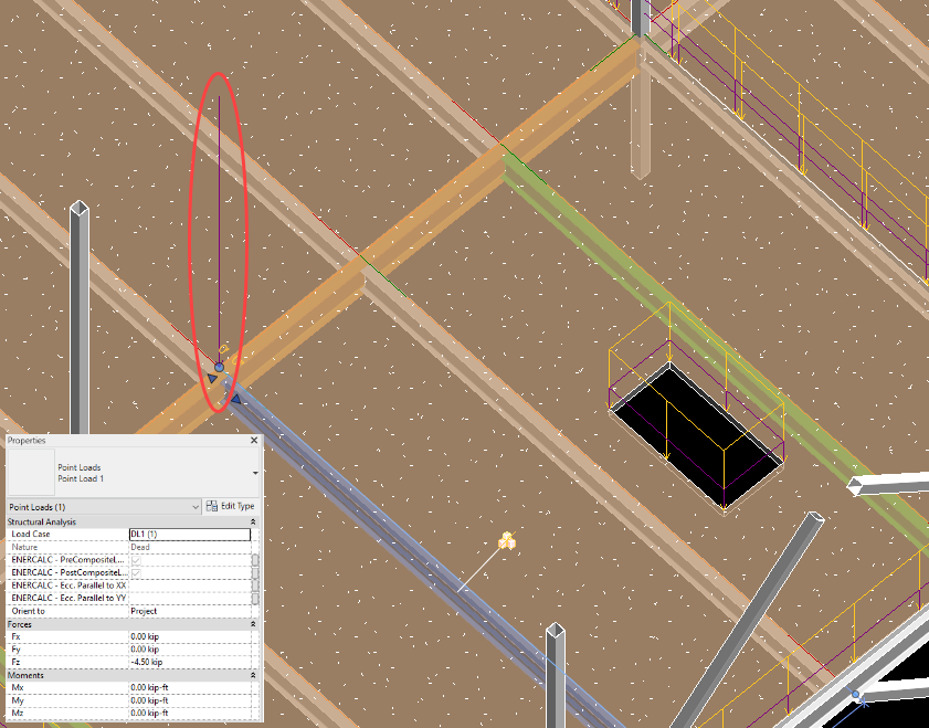
This means that loads at arbitrary intermediate locations along the length of a girder would need to be placed using Analyze > Loads > Point Loads. This native Revit tool permits the user to place a point load of arbitrary magnitude and direction at any location in the 3D model environment. However, the use of free-floating non-hosted loads can be tedious due to the lack of geometry control and doesn’t take full advantage of the geometry and loading information already contained in a typical Revit model. The other loading options available involve varying degrees of automation to reduce this difficulty.
If users choose to model point loads on a girder using non-hosted point loads, the loads will be detected and automatically included in the calculation upon launch, as discussed in “Launching With Revit Non-Hosted Loads”.
Option 2: Load-Linked Beam Reactions
The first and most efficient alternative to using manually applied free-floating point loads is to instead directly design each of the infill beams using ENERCALC for Revit. This allows users to take advantage of “Load-Linking” when designing the girder. This topic is discussed in detail under “Beam/Girder Load Linking”.
Option 3: Hosted Point Loads
If the infill beams supported by a girder are not designed using ENERCALC for Revit, then there will not be any stored reactions available for use via automatic load linking when the girder calculation is launched. This is frequently the case in the early stages of a project before beam design has been performed, as well as in projects where the infill framing are manufactured elements not designed in ENERCALC (i.e., open-web steel joists, cold-formed steel joists, wood joists, etc.).
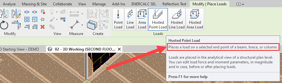
For girder designs where loading linking is unavailable, the next alternative is to apply point loads hosted (Analyze > Loads > Hosted Point Loads) to the bearing end joint of each of the infill beams.
If users choose to model hosted point loads on the ends of the infill beams, the loads will be detected and automatically included in the girder calculation upon launch, as discussed in “Launching With Revit Hosted Loads”.


Option 4: Girder Point Load Generation
Although reactions may be modeled manually at the end joints of infill beam as described in the previous section, this process is time-consuming and necessitates hand-calculation of the appropriate reactions for each beam. This requires knowledge of a variety of information for each individual beam, including the following:
•Beam Span
•Beam Spacing / Tributary width
•Area loads on the roof or floor
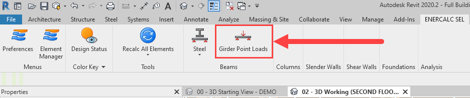
Rather than forcing the user to obtain this information manually, hand-calculate, and manually apply forces, the “Girder Point Loads” tool provides the ability to perform this task automatically by detecting the critical design information from the Revit model. This tool is accessed from the “Beams” panel of the ENERCALC for Revit ribbon tab.
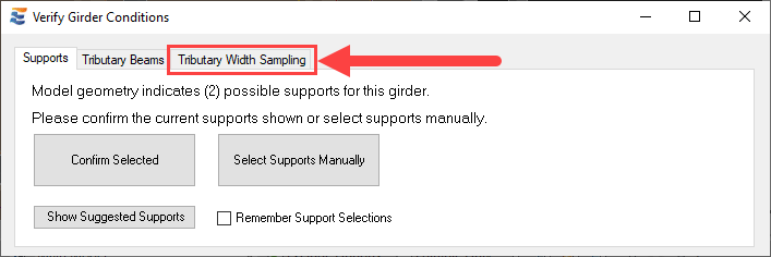
Similar to the launch of a typical beam calculation, the “Girder Point Loads” tool begins with an approval window for the user to verify critical information about the girder. This includes verification of both supports and tributary (infill) beams.
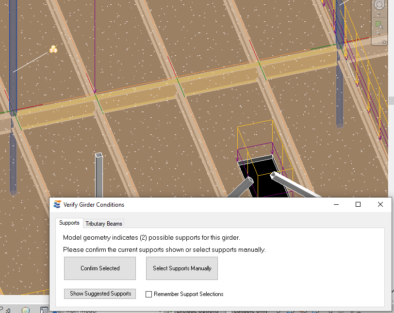

The navigation of this launch window is identical to that described in “Beam Supports” and “Tributary Beams”. When the approval process concludes, the girder point load tool will automatically test each of the tributary beams and detect the information necessary to compute the reaction each will exert on the girder:
•Beam Span
•Beam Spacing / Tributary width
•Area loads on the roof or floor
This information is used to compute an estimated reaction from each infill beam by assuming uniformly loaded simple span behavior:
Reaction = (Area Load * Tributary Width) * Span / 2
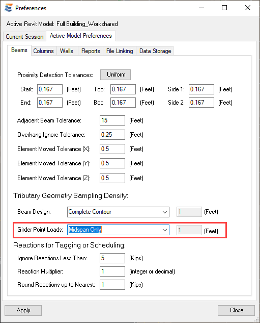
The tributary width is obtained using the same process as previously described in “Tributary Width Sampling” and “Sampling Density Controls”. The density used for sampling may be specified in the ENERCALC for Revit Preferences menu, or may be specified at time of launch.
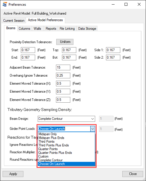
When the sampling density is set to “Choose On Launch”, an additional tab will appear on the launch window for the user to choose a sampling density.
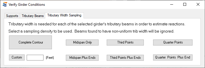
Once trib sampling is complete for a given beam, the individual tributary width measurements are compared to each other to validate the assumption of uniformly loaded behavior (excepted when sampling at “Midspan Only”, in which case there is only one value). A beam whose tributary width measurements along the beam do not match will not be used for computing reactions. As noted in the approval window, the user has the ability to specify a wide variety of different sampling conditions, ranging from sparse (Midspan Only) to very dense (Complete Contour). Users should bear in mind that denser sampling modes are more likely to detect subtle variations which render a contour non-uniform (and therefore result in a beam being disqualified for automatic reaction generation by this tool), while sampling at “Midspan Only” will never result in a beam being disqualified from point load generation.
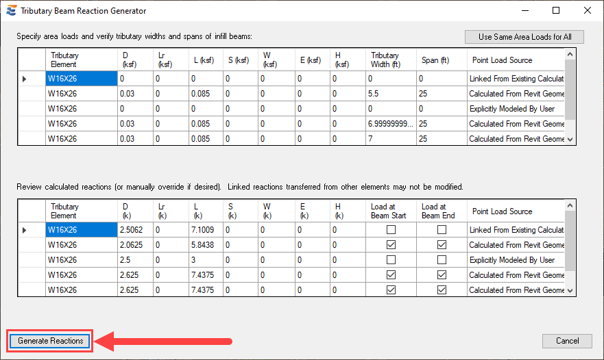
When the tributary width sampling process is complete for all tributary beams, the Reaction Generator window will load. The window is divided into two halves, where the upper summary table displays the input data detected for each infill beam and the lower half displays the reactions computed from this data.

For ease of viewing, the Reaction Generator tables may be expanded by using the drag control at the lower edge of the window. Enlarging the window will cause both of the tables to expand.

Similar to the calculation launch window, the Reaction Generator form allows the user to retain full navigation of the Revit interface to perform a variety of actions, including changing the active view, opening or closing views, and using dimension annotation or measure tools to verify the data shown in the table.


Selecting a specific row in the Reaction Generator tables automatically triggers selection of the corresponding element in the active Revit view.

When Revit floors and area loads are not present on the tributary beams, the area loads in the input table will initially be shown with zero magnitudes. The desired area loads for reaction calculation may be supplied manually by typing in the appropriate cells. The resulting reactions will update in the lower table automatically.

In addition to manually setting the area loads, the user may directly override the reactions in the lower table by typing in the appropriate cell.

Different area loads may be supplied in each row or, if desired, the same area loads may be applied to all reaction calculations in the table by clicking the “Use Same Area Loads for All” button in the upper right hand of the window. Using this button will populate all subsequent rows with the first user-supplied area load magnitudes found in the table.

When Revit floors and area loads are found on the tributary beams, the magnitudes of the area loads will automatically populate in the Reaction Generator input table. The load magnitudes may be manually overwritten in the table if desired and the reactions will update accordingly, but this will not cause any change to the properties of the actual area load elements in the Revit model.

Note also that the “Girder Point Loads” tool also has the ability to interpret and display reaction loads that have already been applied to the girder by other means. This includes alerting the user of point loads created via Option 2 and Option 3 discussed previously, but not Option 1. Non-Hosted point loads referenced above as Option 1 are floating in 3D space and do not have a direct relationship with the girder that can be discerned by this tool. Even though not displayed in the table, non-hosted loads may still be present in the model and will be included in the girder design calculation if they are located appropriately.
The “Girder Point Loads” tool automatically considers the presence of pre-existing reaction forces when evaluating whether a reaction should be calculated for each individual beam. The following logical framework establishes precedence for obtaining reactions on a beam-by-beam basis:
•If a girder has explicitly modeled loads as non-hosted Revit load elements (Option 1), these forces will not be presented for review in the reaction table. Any non-hosted loads will be additive with the loads generated by the “Girder Point Loads” tool. It will not remove or replace them.
•If a particular infill beam has previously been designed using ENERCALC for Revit and already has a reaction at the connection to the girder via “Load-Linking” (Option 2), that reaction will be presented in the girder point load table.
•If a particular infill beam has NOT been previously been designed using ENERCALC for Revit, the program will look to see if the user has explicitly applied a reaction as a hosted load at the end of the infill beam (Option 3). If so, that reaction will be presented in the girder point load table.
•If a particular infill beam has NOT been designed using ENERCALC for Revit (Option 2), and if the user has NOT explicitly applied a reaction as a hosted load at the end of the infill beam (Option 3), then the girder point load tool will present the span, tributary width, and area load found for that beam, along with the resulting estimated reaction force (if the beam is not disqualified on the basis of a non-uniform tributary width). The user may then review this information and/or interact with the table values as previously described.
•If an infill beam is eligible for reaction generation due to not meeting Option 2 or Option 3, but is found NOT to have uniform tributary widths, the girder point load tool will place an entry in the table with no load applied. This is for the user’s convenience to be alerted that the member was found, despite the fact that the program could not calculate an accurate reaction for that end of the member.
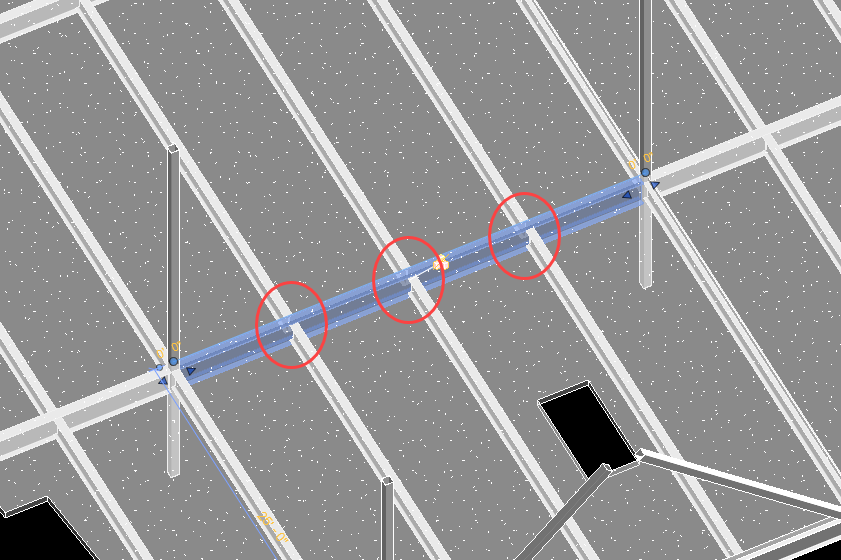
An example girder scenario is shown below, with all of the significant conditions that influence the information presented to the user in the girder load generator table.

Launching the “Girder Point Loads” tool for this girder will provide a summary of the beams whose reactions are already present in the Revit model, as well as the beams for which reactions are calculated. As discussed previously, it is necessary to sample the infill beam tributary widths at a density high enough to detect the opening in order to reproduce the results shown here.
Infill beam #1 is automatically found to have existing reactions stored from its own design calculation. The “Point Load Source” column at the right end of the table indicates “Linked From Existing Calculation”. As a result, the tributary width is not sampled and no model data are reported in the input table. The forces shown in the lower half of the window on the reaction table are the stored reactions found from the existing calculation. New reaction forces will NOT be generated for this beam.

Because of the high-density sampling which detects the floor opening, infill beam #2 is automatically found to have non-uniform tributary width along its length. The “Point Load Source” column at the right end of the table indicates “Non Uniform Beam”. As a result, the tributary width, span, and area loads found in the model are reported in the input table for reference only. There is no calculated reaction shown in the lower half of the window on the reaction table. New reaction forces will NOT be generated for this beam.

Infill beam #3 is automatically found to have pre-existing hosted point loads at the end joint which bears on the girder. The “Point Load Source” column at the right end of the table indicates “Explicitly Modeled By User”. As a result, the tributary width is not sampled and no model data are reported in the input table. The forces shown in the lower half of the window on the reaction table are the modeled reactions already found in the Revit model on the end of the beam. New reaction forces will NOT be generated for this beam.
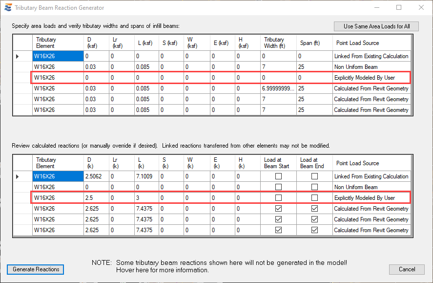
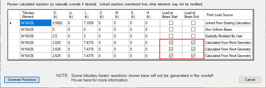
The remaining infill beams, #4, #5, and #6 are not found to have any constraints or existing loads that prevent tributary width sampling. As a result, they are sampled at the density specified and the tributary width, span, and area loads found in the model are reported in the input table. The “Point Load Source” column at the right end of the table indicates “Calculated From Revit Geometry”. The calculated reactions shown in the lower half of the window on the reaction table are the proposed reactions that will be created automatically when the user clicks the “Generate Reactions” button.

Prior to generating these reactions in the Revit model, the user has the ability to manually select whether the reactions will be created at both the start and end of the beam. This selection is made using the checkboxes in the “Load at Beam Start” and “Load at Beam End” columns. Unchecking any of these boxes will mean that no reaction is generated at the specified end of that particular beam. The “Start” and “End” definitions are based on the Revit end definitions found in the model.
Note also that when any conditions are found that preclude the creation of new reactions, the generator window will include a warning reminding the user.
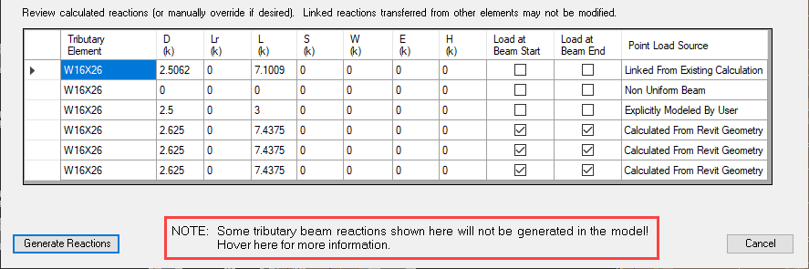
Hovering over this notification with the cursor displays a tooltip balloon with more detailed information, including the sampling density that was use, and steps the user can take to consider force effects from the disqualified infill beams.

When the user has reviewed and verified (or modified as needed) all reaction information in the table, the reactions may be automatically created in the Revit model by clicking the “Generate Reactions” button.
The “Generate” command results in two processes:
1.Any existing reactions that were previously created by the “Girder Point Loads” tool will be automatically removed.
a.This prevents the accidental creation of duplicate loads.
b.Hosted point loads created manually by the user will NOT be removed.
c.Non-hosted point loads will not be removed.
2.Following the removal of existing reactions, the new reactions specified in the table will be generated.
a. Note that the reactions will only be generated at beam end locations where the “Load Beam At…” box is checked on.
b.The reactions will appear in the Revit model as Hosted point loads on the end joints of the applicable beams.
c.These loads will then be available for automatic detection when a beam design calculation is launched for the girder.


During future re-runs of the “Girder Point Loads” tool, the program will recognize these reactions as having been created by ENERCALC for Revit rather than by the user. As a result, the reactions will be eligible for removal and replacement when the tool is used again in the future. In addition, if the hosted point loads explicitly modeled by the user are manually deleted, then infill beam #3 will become eligible for reaction generation during future re-runs of the “Girder Point Loads” tool. Similarly, if the existing ENERCALC for Revit calculation on infill beam #1 were to be deleted, this beam might also become eligible for reaction generation, depending on the selected sampling density.
 <
<