Sampling Density Controls |
  
|
Sampling Density Controls |
|
In order to give the user control over this testing and calculation process, the ENERCALC for Revit Preferences menu provides settings in Preferences > Beams > Tributary Geometry Sampling Density.
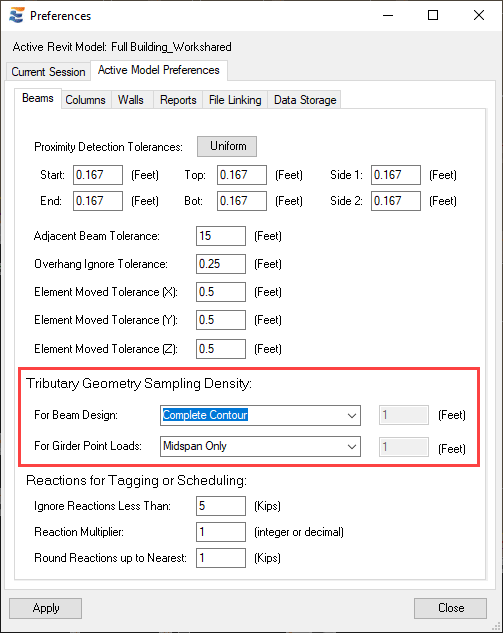
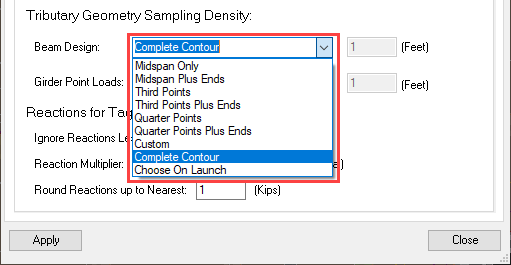
The default setting is “Complete Contour”, with additional options as follows:
Note: The beam tributary width sampling density is a project-level change that applies to all team members who create beam calculations in the project. Modifying this property in a workshared Revit project will result in a notification.
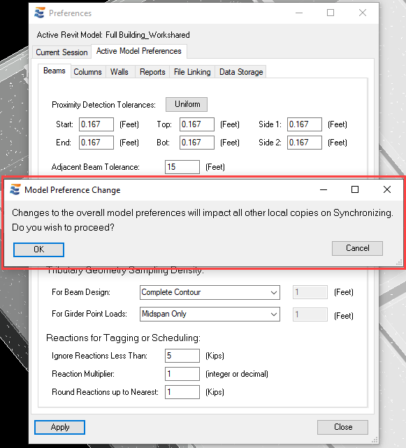
Since the setting is stored in the database of the Revit project, it is necessary for members of the design team to synchronize in order to obtain the most recent setting. If the setting is changed and team members do not synchronize their local Revit files with the central file, they will be using whatever sampling density was previously set.
As discussed later in greater detail, the changing of this overall Preference setting does not alter the behavior of existing beam calculations. Instead, each individual calculation will automatically retain the density that was used during its previous launch. This information stored individually on each calculation takes precedence over the Preference setting. The Preference setting is used by default on all newly created calculations.
The tributary sampling performed by each option is as follows:
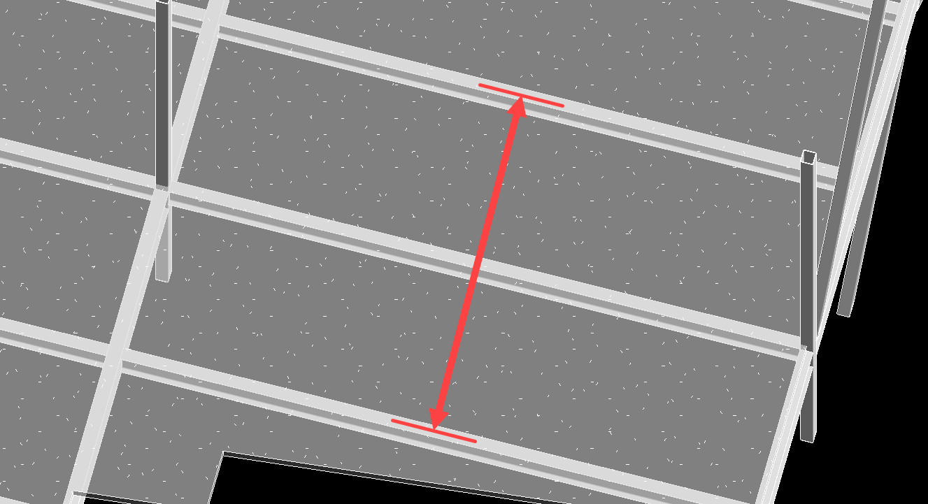
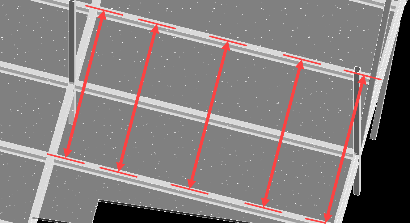
•“Midspan Only”: The beam’s tributary width is calculated at one location only, at the exact mid-length of the beam (L / 2).
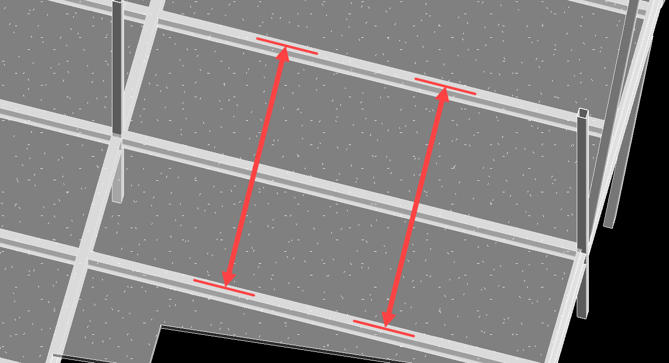
•“Third Points”: The beam’s tributary width is calculated at 2 locations, at the third points of the beam (L / 3 and 2L / 3).
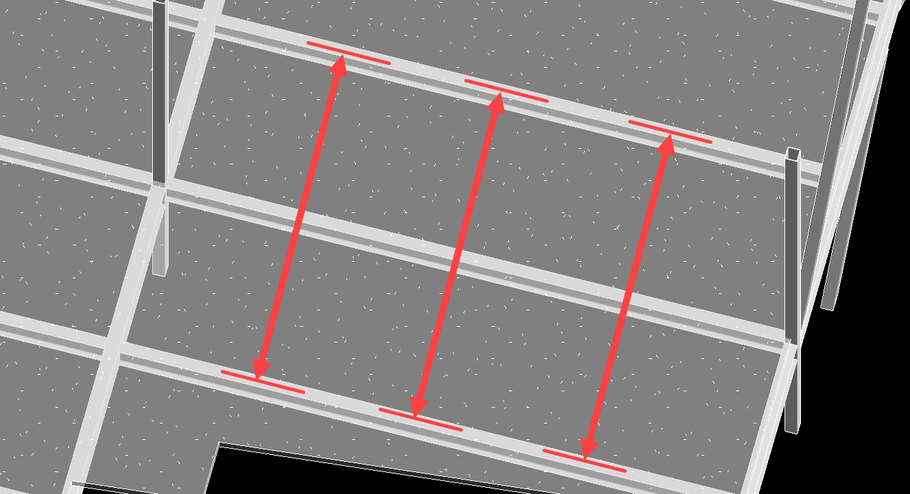
•“Quarter Points”: The beam’s tributary width is calculated at 3 locations, at the quarter points of the beam (L / 4, 2L / 4, 3L / 4).
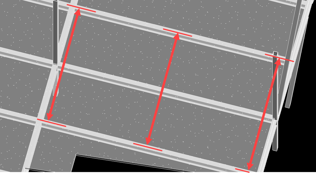
•“Midspan Plus Ends”: The beam’s tributary width is calculated at 3 locations, at the exact mid-length of the beam (L / 2) and 6” from each end point. The sampling is performed a short distance from the extreme end point to avoid irregular conditions that complicate the sampling.
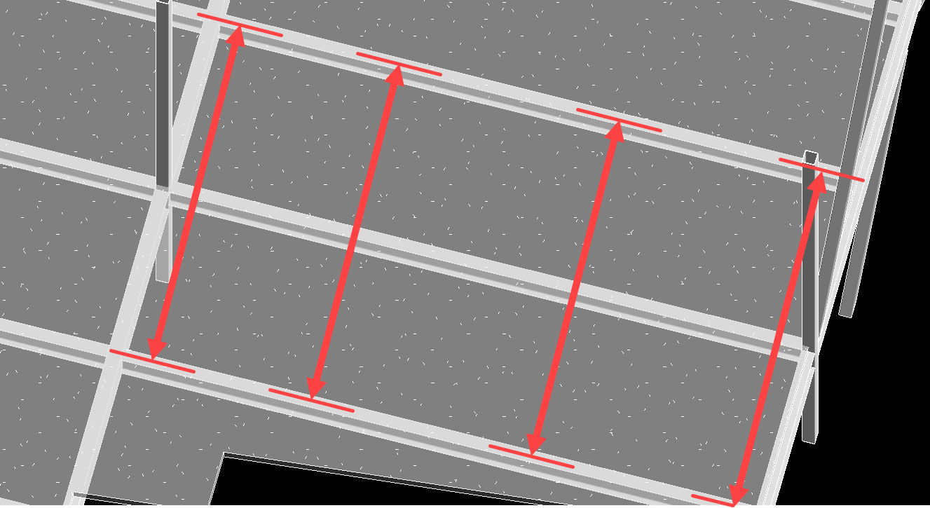
•“Third Points Plus Ends”: The beam’s tributary width is calculated at 4 locations, at the third points of the beam (L / 3 and 2L / 3) and 6” from each end point. The sampling is performed a short distance from the extreme end point to avoid irregular conditions that complicate the sampling.
•“Quarter Points Plus Ends”: The beam’s tributary width is calculated at 5 locations, at the quarter points of the beam (L / 4, 2L / 4, 3L / 4) and 6” from each end point. The sampling is performed a short distance from the extreme end point to avoid irregular conditions that complicate the sampling.
•“Custom”: When the drop-down is toggled to “Custom”, the user will have access to the input box to specify an arbitrary spacing for tributary width sampling locations. This will result in sample points 6” from each end point and at the specified spacing.
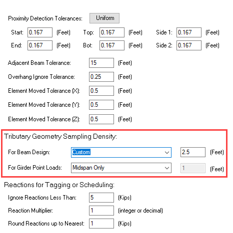
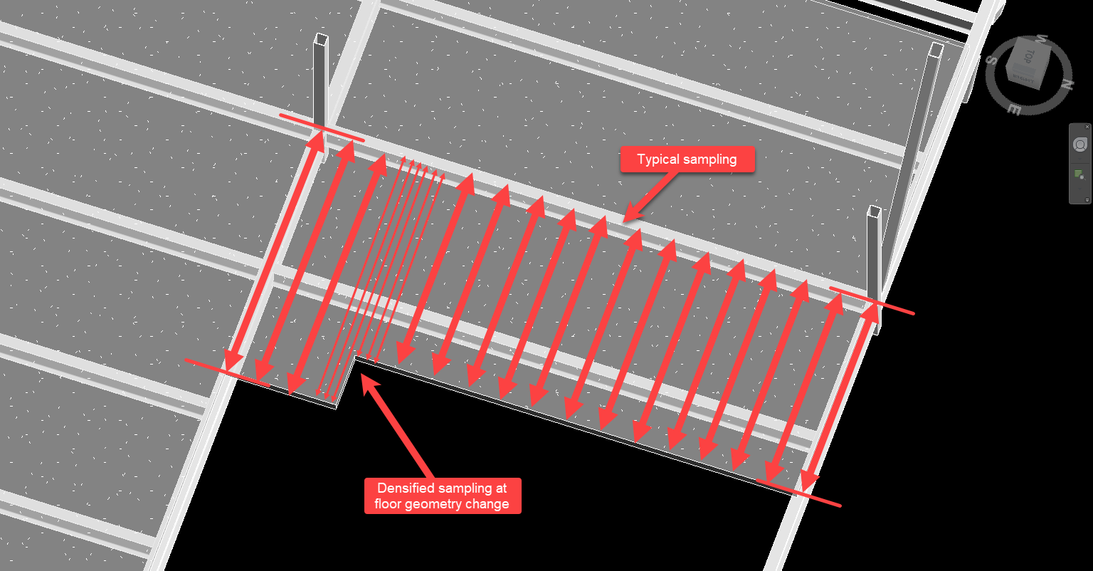
•“Complete Contour”: This setting will result in an autonomous process that dynamically senses varying conditions along the beam and produces an appropriately dense sampling contour. When generating a complete contour, the beam is tested at the extreme end points for a higher degree of accuracy, rather than using a 6” standoff. The beam will be automatically tested at 1’-0” on-center, and then densified at finer spacings in any location where tributary width changes and floor discontinuities are discovered.
The tributary sampling options described above are arranged in order from lowest density to highest density. This rise in sampling density also corresponds to marginally slower computation times when launching a beam calculation. The lowest density options execute fastest, but will produce less detailed tributary width contours. While highly efficient for beams with uniform tributary geometry, lower density settings are problematic when a beam manifests variations along its length, including floor openings, floor edge changes, and beam framing changes.
Beams with any form of observable variation in tributary geometry to be captured in the design are best served by using the “Complete Contour” setting. Discrete sampling modes often prove useful in situations where the user desires to perform a simple calculation that does not depict the full complexity of a Revit model, or when engineering judgment dictates that a lower sampling density will yield satisfactory results. For example, sampling at midspan only allows the user to ignore miscellaneous slab variations, such as small mechanical piping openings. Specific use Revit model cases are discussed in subsequent sections.
Rather than directly selecting one of the above sampling densities from the Preferences menu, the user alternatively may opt to “Choose On Launch” for each individual calculation. This allows for generating many different beam calculations sampled at different densities without repeatedly modifying the overall Preferences setting for the project.
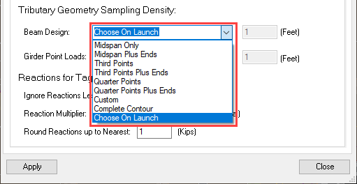
When the Preference is set to “Choose On Launch”, an additional approval tab will be added to the calculation launch window for the user to select a sampling density where applicable. This extra tab will not be included when the beam being launched does not have area-loaded floors present in the Revit model.
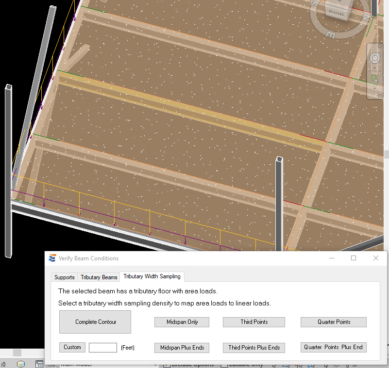
After a sampling density is selected (either via Preferences or during launch), ENERCALC for Revit will test the beam at an array of locations corresponding to the chosen density and construct a tributary width contour. Once the tributary width contour has been computed, the individual points will be evaluated to determine if they constitute a uniform load, a linear varying load, or an irregular load and will be mapped to the ENERCALC SEL calculation accordingly.
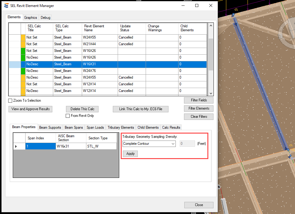
In order to ensure consistent calculation results and limit repetitive mandatory interaction with approval steps during launches, ENERCALC for Revit automatically stores the most recent sampling density selected for each individual beam. As a result, users will NOT be forcibly prompted to select sampling density more than once on a given beam calculation. Future launches of the calculation will use the same sampling density used on the previous launch. If at any point the user wishes to view or change the sampling density for a particular beam, this may be done via the Element Manager window. When a beam calculation is selected in the Element Manager, detailed information automatically populates in the lower half of the window.
From this drop-down menu, the user may manually select any of the alternate density modes discussed above, or may choose to revert the beam to whichever option is set in the Preferences menu.
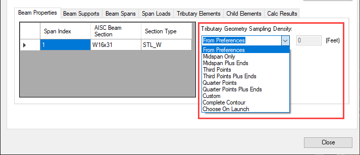
Choosing an option from this menu and clicking the “Apply” button will cause the selected sampling mode to be used on the next launch of this particular beam calculation. Setting this option to “Choose On Launch” or setting to “From Preferences” when the overall preference is set to “Choose On Launch” will cause the user to again be prompted to select manually on the next launch of this beam calculation.
 <
<