Tributary Width Sampling |
  
|
Tributary Width Sampling |
|
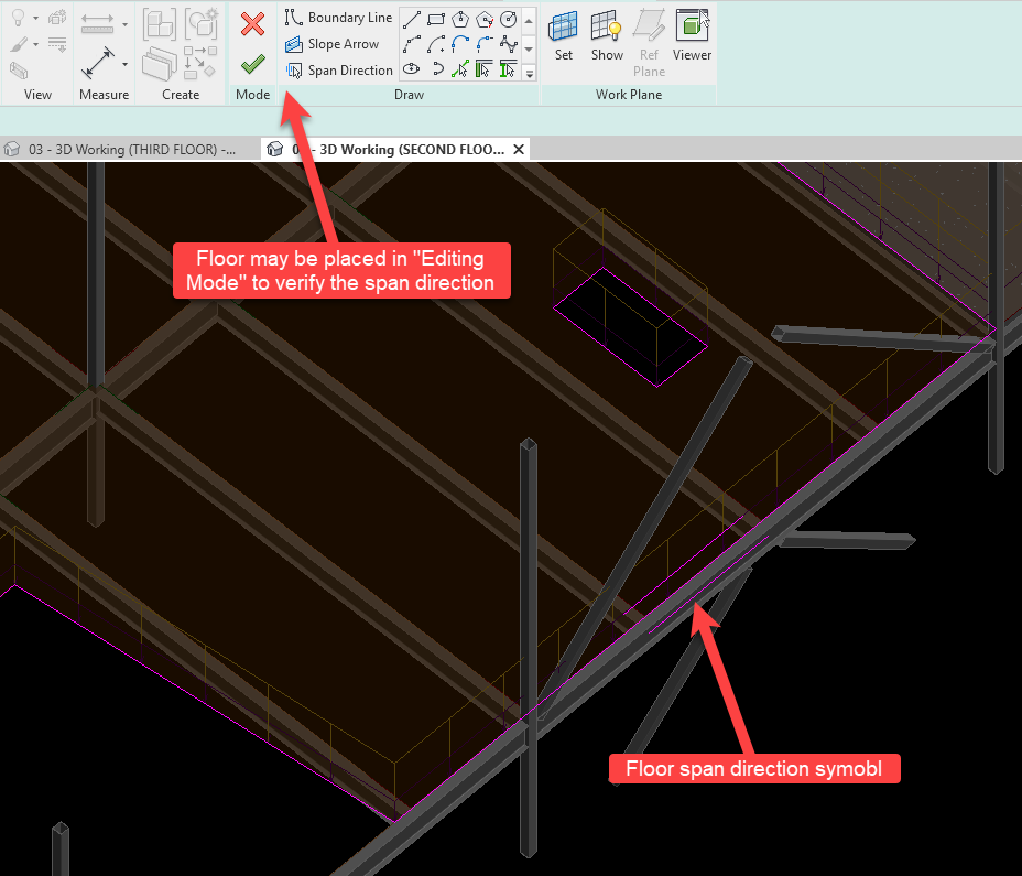
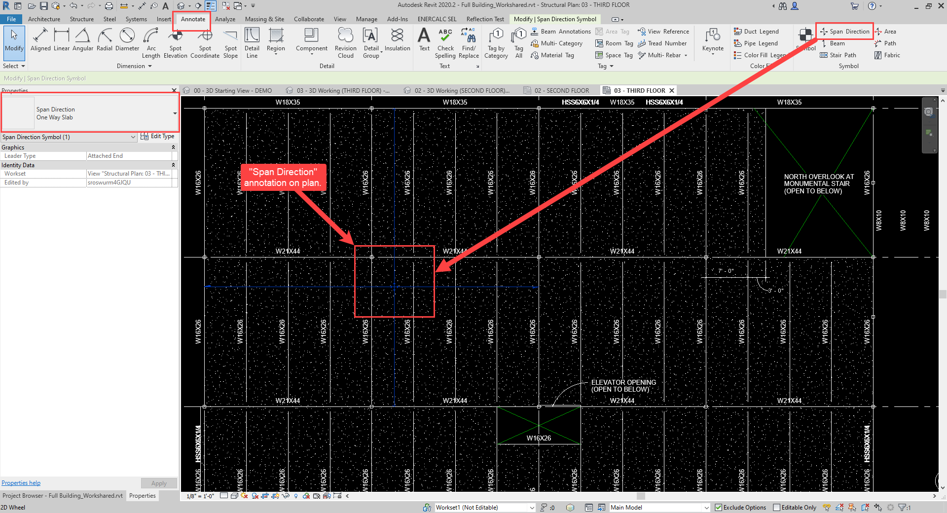
ENERCALC for Revit makes use of the floor geometry relative to the beam to be designed in order to map area loads into equivalent linear loads. This is accomplished by testing the beam at a number of locations along its length in order to compute the instantaneous tributary width at each. Tributary width testing is performed by searching on each side of the beam in a direction parallel to the deck span direction specified in Revit for the floor.
At any given point on the beam, tributary widths are defined by locating nearby constraints on each side of the beam. The following Revit element types are eligible for use in defining tributary width:
•Structural Framing as beams
•Structural Walls
•Structural Floor edges (i.e., openings or perimeters)
The following Revit element types are not eligible for use in defining tributary width:
•Structural Framing as vertical bracing
•Structural Framing as horizontal bracing
•Non-Structural Floor edges
•Structural Foundations
•Structural Walls with a non-bearing usage type
•Non-Structural Walls
•Any other non-structural element
Once the nearby constraints are identified, the following rules dictate the tributary width at a given location on a beam:
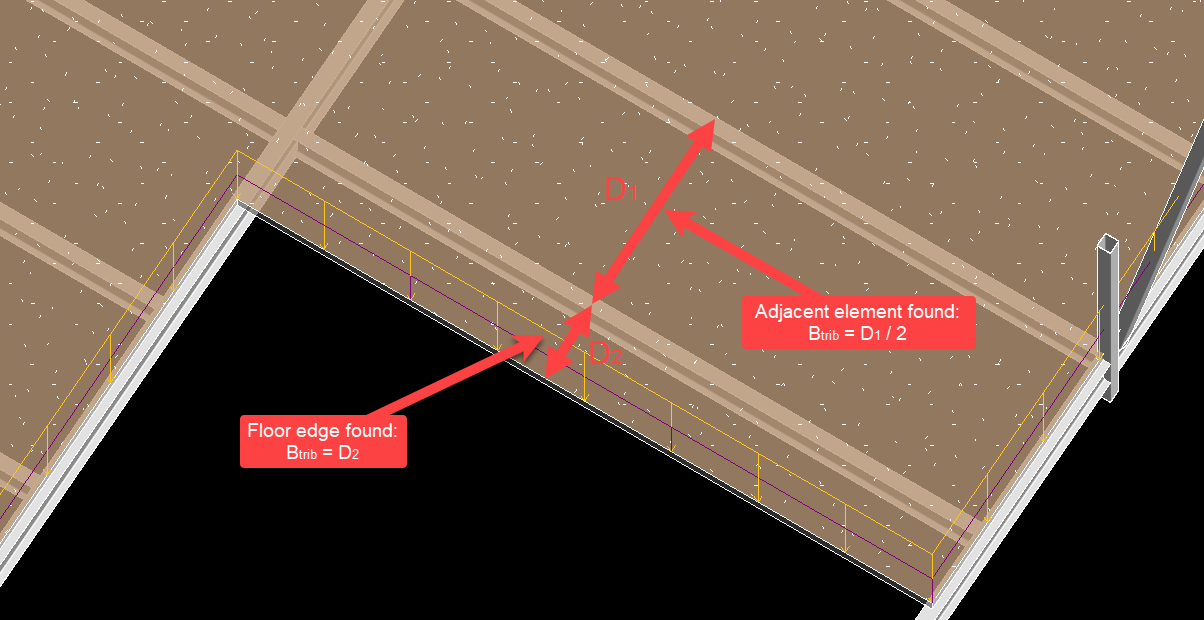
1.When an eligible adjacent element (structural beam or structural wall) is found: The tributary width in that direction is taken as half the distance from the designed beam to the nearby element (simple-span floor behavior is assumed).
2.When a floor edge is found: The tributary width in that direction is taken as the full distance from the designed beam to the floor edge (indicating a cantilever floor).
3.If both multiple edges and/or elements are found nearby, the nearest is taken as the limiting constraint for tributary width, and tributary width is computed according to 1) or 2) as applicable.
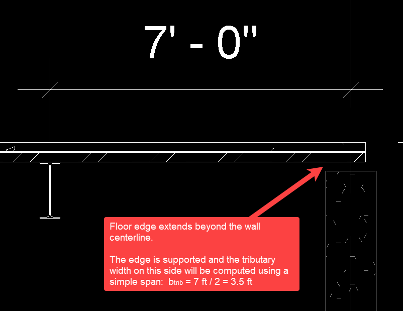
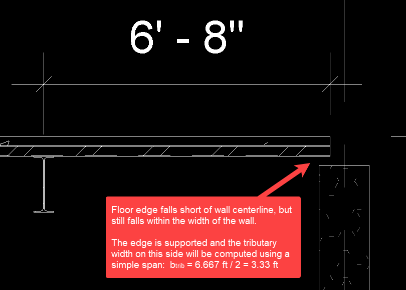
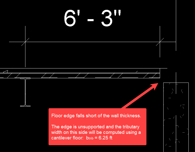
4.If a floor edge coincides closely with a beam or wall, the edge is automatically evaluated to see if it is supported or falls short, creating a cantilever condition. This check is performed using the thickness of the wall or width of the beam.
Determining both tributary width and area load is adequate to compute an instantaneous linear load magnitude at any given location. Doing so for multiple points along a beam results in a linear load with either constant or varying magnitude. The location and spacing of tributary width sampling is discussed in the next section.
There is no load contributed to a beam by a floor whose span direction is found to be parallel to the beam. Due to this provision, it is always expected that elements such as girders or miscellaneous framing (i.e., framed opening beams) oriented parallel to the floor will reflect no line loads mapped from floor area loads when the calculation in displayed in ENERCALC SEL.
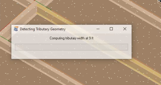
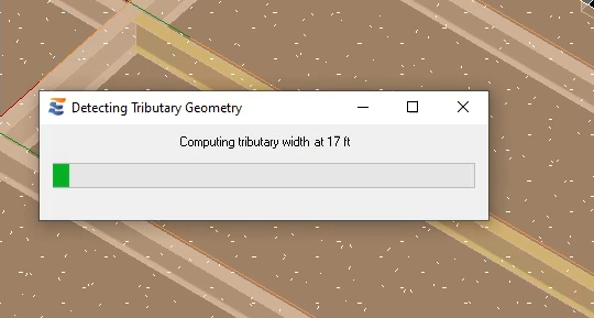
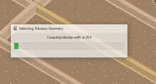
When the beam calculation is launched, the user will notice that ENERCALC for Revit automatically performs tributary width sampling when a floor element is present on the beam. This short intermediate step during launch is marked by a progress bar showing the progress of sampling along the length of the beam. In most cases, the progress bar may not be visible due to very fast execution of the sampling.
When the calculation appears in the ENERCALC SEL interface, the equivalent linear loads derived from the area loads and tributary geometry will be automatically displayed. Although some special cases may arise, the general approach is that fully uniform loads will be displayed in the “Loads All Spans” tab, while segmented loads, linear varying loads, and loads with redundant load cases will be displayed in the “Span Loads” tab. Loads generated from Revit area loads will be displayed using the area load magnitudes and tributary widths detected in the Revit model.
The implementation of area loads for various conditions is discussed in subsequent sections.
 <
<