Beam/Girder Load Linking |
  
|
Beam/Girder Load Linking |
|
When designing beams and girders using ENERCALC for Revit, reaction forces from structurally connected elements will automatically be incorporated into subsequent calculations further down in the load path.
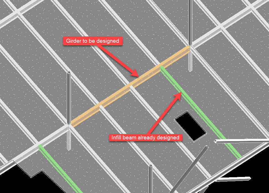
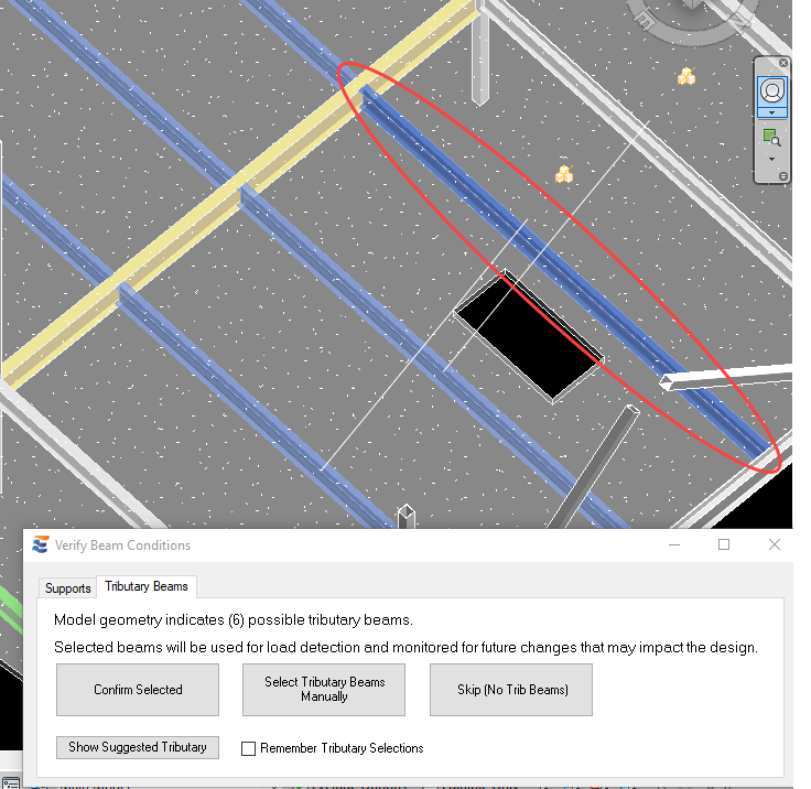
As discussed previously in “Beam Supports”, the user will be prompted during launch of the infill beam calculation in order to verify its structural relationship with the girder.

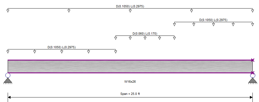
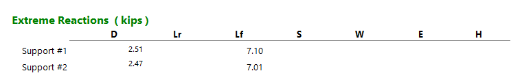
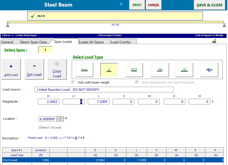
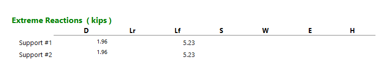
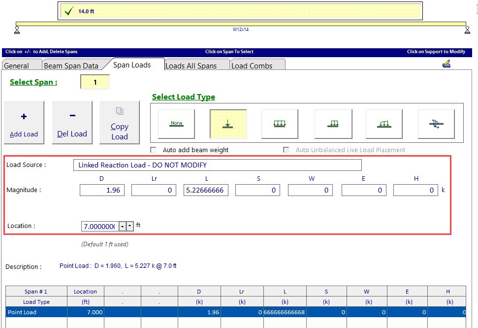
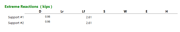
Design of each infill beam results in end reactions calculated in ENERCALC SEL, which are then stored in the Revit model for later use.
When subsequently launching a calculation for the girder, the user will again be prompted to verify a structural relationship with the beam.
Once the structural relationship between the beam and girder has been confirmed during launch, the beam reaction is automatically included in the girder calculation with no additional effort from the user.

Users should be aware that “Load-Linking” of reactions forces between beam calculations is active even when the beam to be designed is not acting purely as a girder. “Load-Linking” applied even when the beam to be designed exhibits both beam and girder behavior. As an example, consider the elevator shaft opening framing shown below. The framing assembly uses several layers of “Load-Linking” transfer, which is achieved by designing the beams in order of load path.

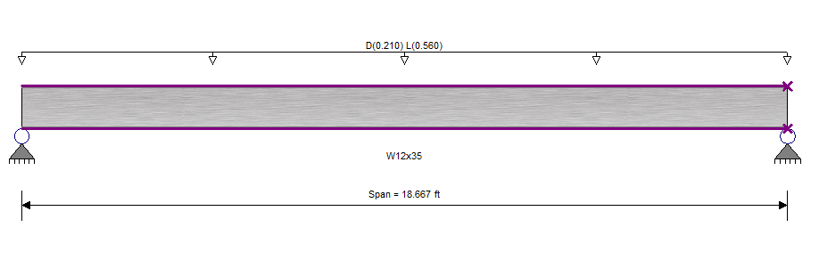
During the design of the basic floor beam, there are no linked reactions involved.
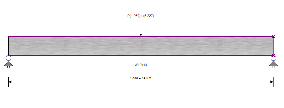
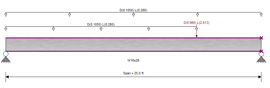
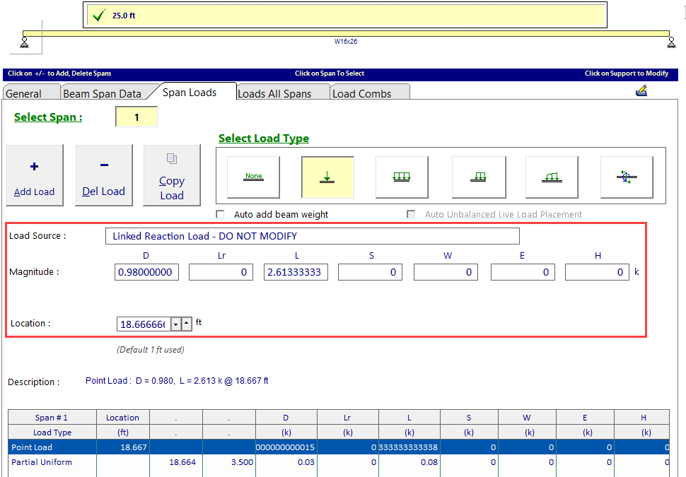
The design of the short girder at the front of the shaft then automatically considers this reaction and locates it appropriately.
Design of the opening edge beam then automatically considers the loading associated with area loads on the floor and the reactions exerted by the short girder.
 <
<