Launching With Revit non-Hosted loads |
  
|
Launching With Revit non-Hosted loads |
|
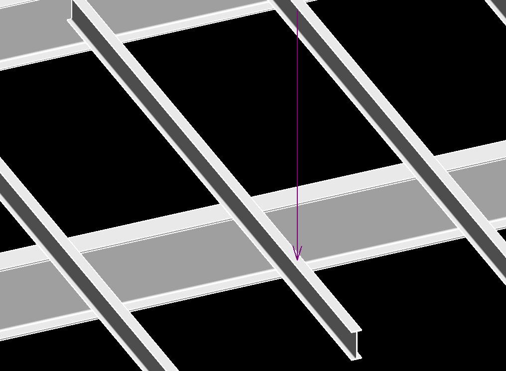
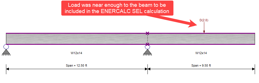
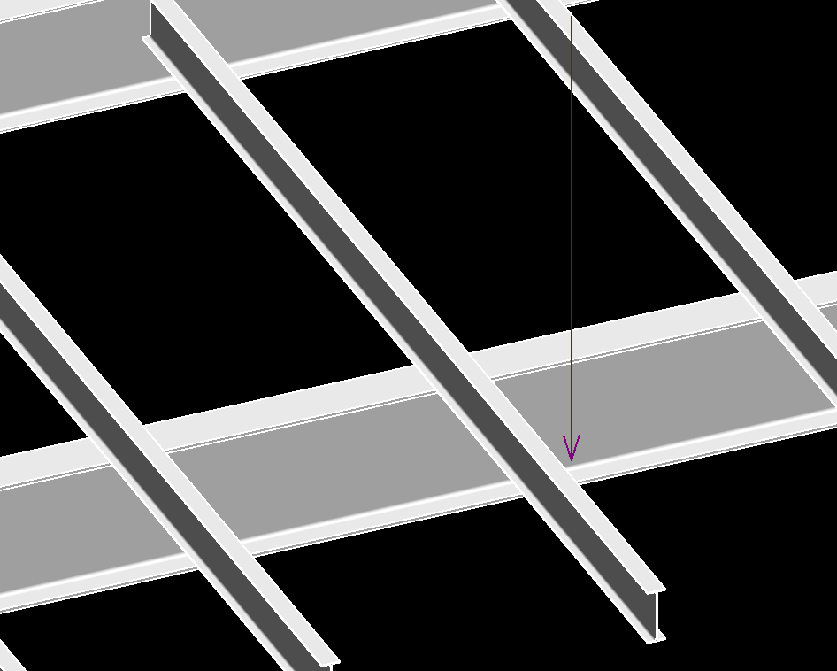
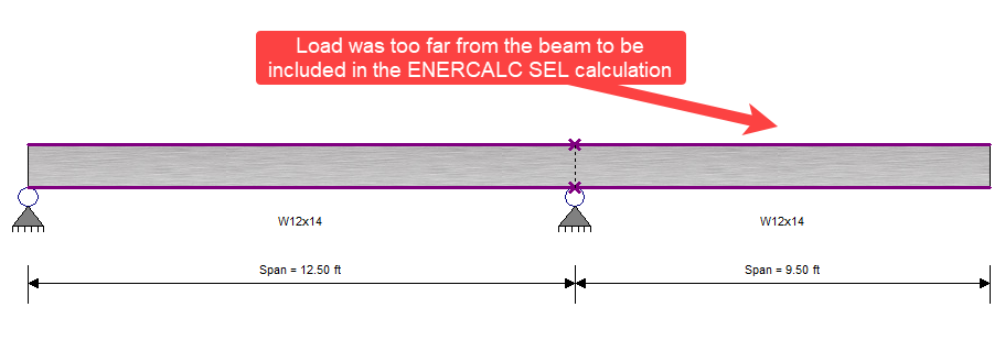
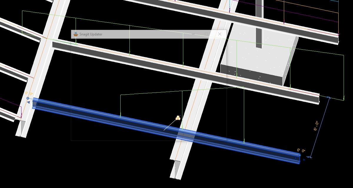
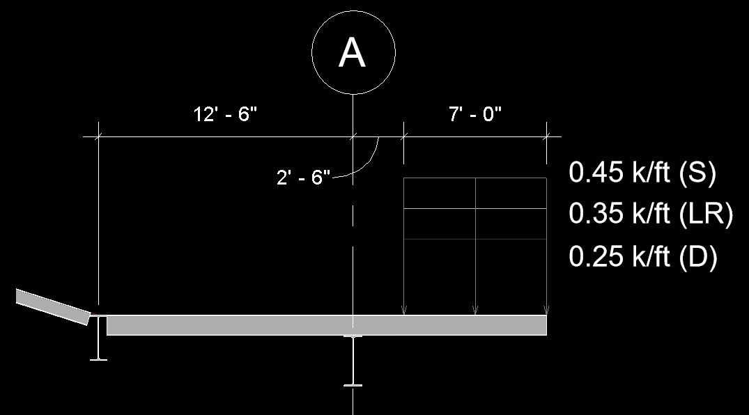
During the beam calculation launch process, non-hosted load elements are detected by physical proximity to the beam. Physical proximity is tested with a tolerance of 2 inches beyond the face of the beam in each direction (top, bottom, left side, right side, start, end). Any non-hosted load falling within this boundary will be considered for inclusion in the calculation.
Note: To be included in a calculation, non-hosted line loads and point loads must be found in direct proximity to the beam, even when a floor element is present. ENERCALC for Revit does NOT consider the transfer of force effects of miscellaneous linear loads or point loads found on a floor in between beams.
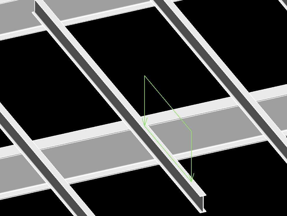
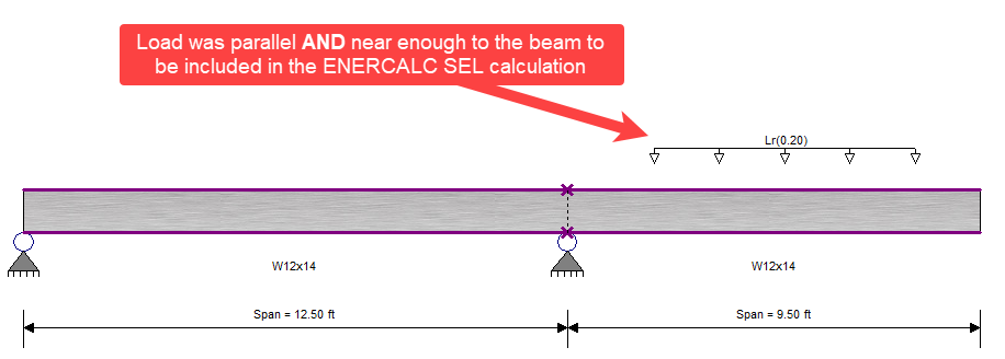
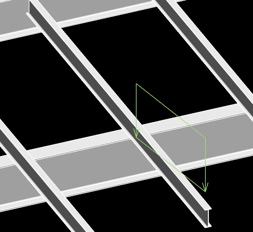
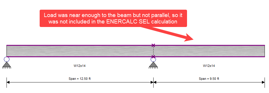
In addition to proximity, linear loads are also tested for alignment. Linear loads must be oriented parallel to the designed beam in order to be included.
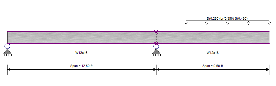
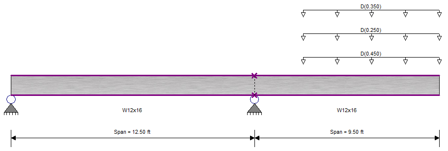
Non-hosted load elements that cross elements designated as supports for the loaded member are automatically divided and will appear in the ENERCALC SEL interface as separate loads applied to the two adjacent spans.
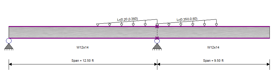
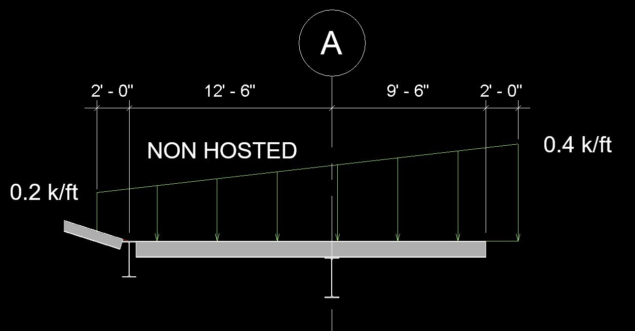
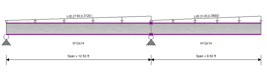
Non-hosted loads that extend beyond the ends of the beam will be interpolated as necessary to set the appropriate magnitudes at the ends of the beam.
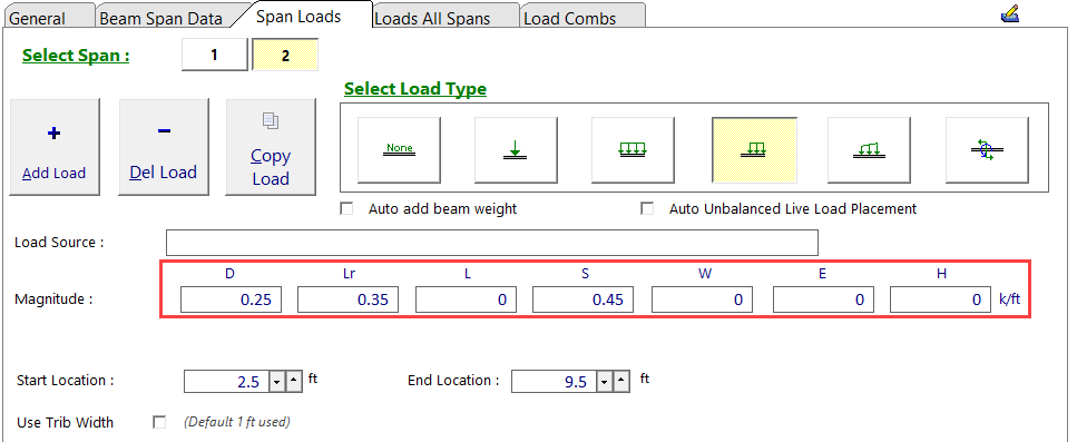
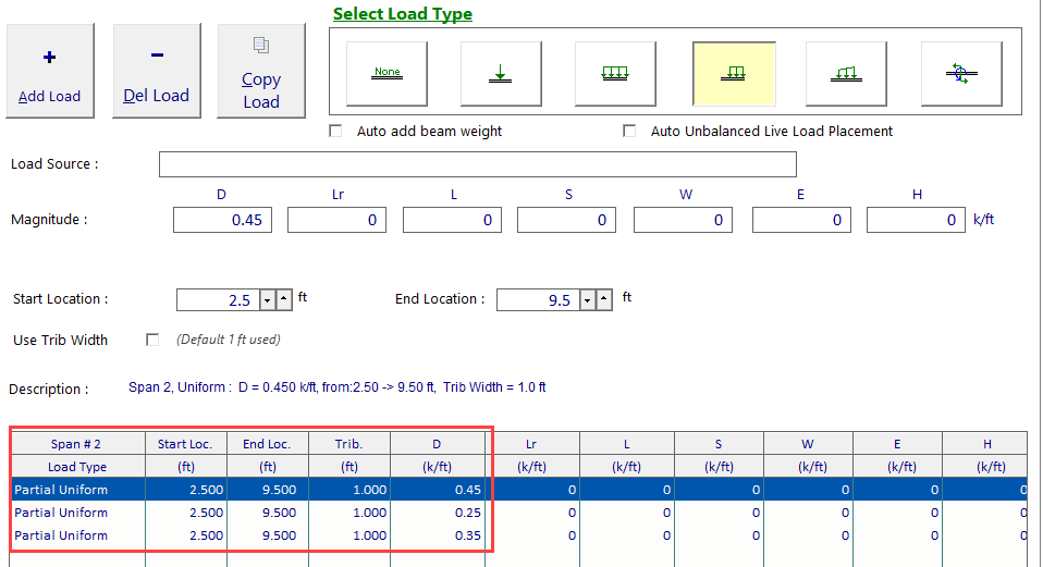
When multiple non-hosted load elements overlap with identical geometry but differing load cases, they are automatically consolidated to a single load item in the ENERCALC SEL interface, with the magnitudes corresponding to each load case preserved for individual review and modification.
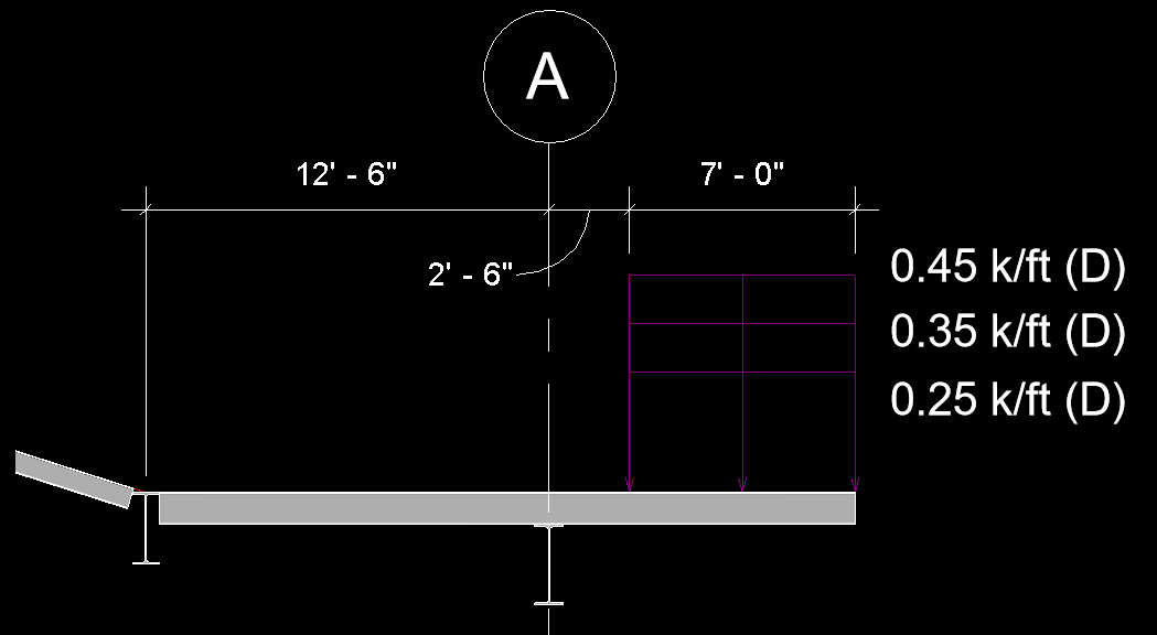
When multiple non-hosted load elements overlap with identical geometry and repetitive load cases, they are not consolidated but instead will appear as individual load items in the ENERCALC SEL interface.
 <
<