Resolving Ambiguous Support Conditions |
  
|
Resolving Ambiguous Support Conditions |
|
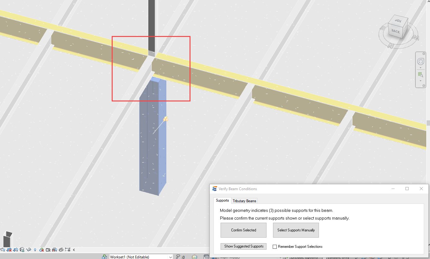
In some framing conditions, ENERCALC for Revit’s detection process may identify multiple possible support elements very close to each other. A number of these ambiguities are resolved on the fly without user input by the following precedence rules:
1.When two possible supports coincide at the same location, priority is given to the element whose solid centroid is lower in 3D space. According to this logic, framing conditions with stacked columns will not result in ambiguity warnings because the lower of the two columns is suggested by default.

Similarly, a wall below with column above condition will not result in an ambiguity warning because the lower of the two (the wall) is suggested by default.
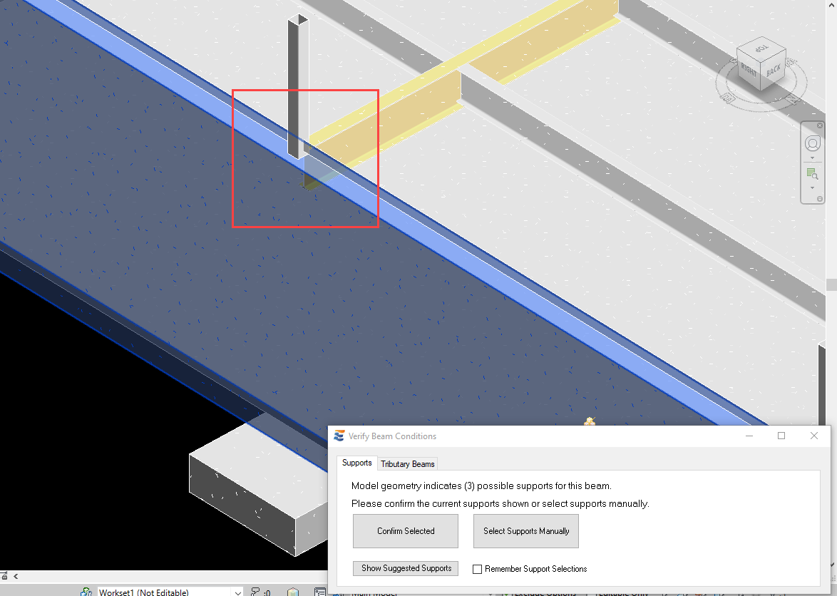
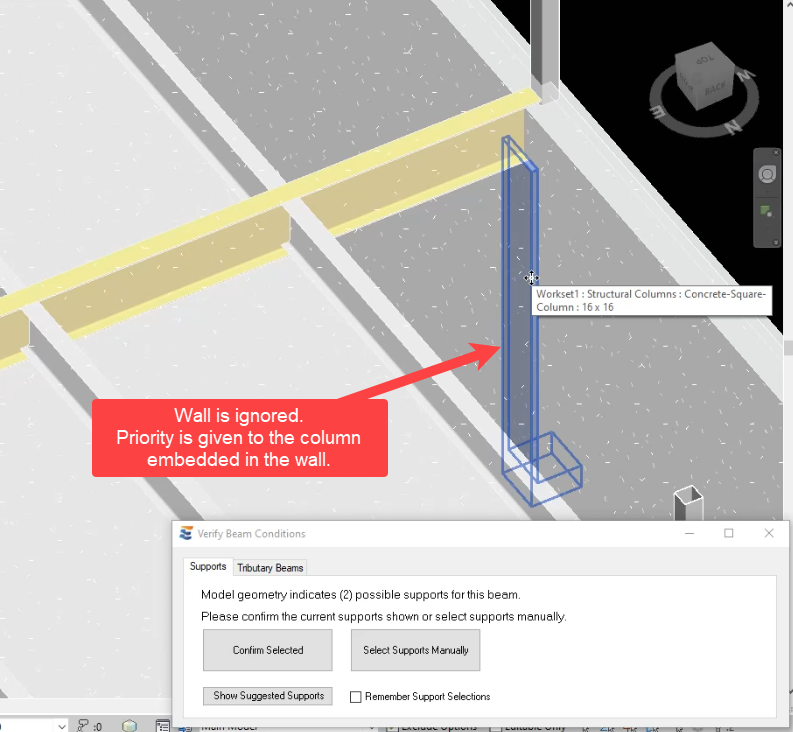
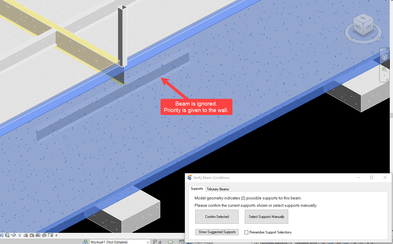
2.If the coincident supports have closely matched physical locations in space such that the “lowest support” test is inconclusive, then the following priority is applied:
a.Columns have priority over walls and beams
b.Walls have priority over beams
For any framing condition where the user’s design intent does not align with the logic used to automatically limit ambiguous conditions, the load path may always be corrected by choosing the “Select Supports Manually” button. As discussed in “Manually Selecting Support Conditions”, the user may manually choose from ANY beam, column, or wall element that is found in physical proximity to the beam to be designed.
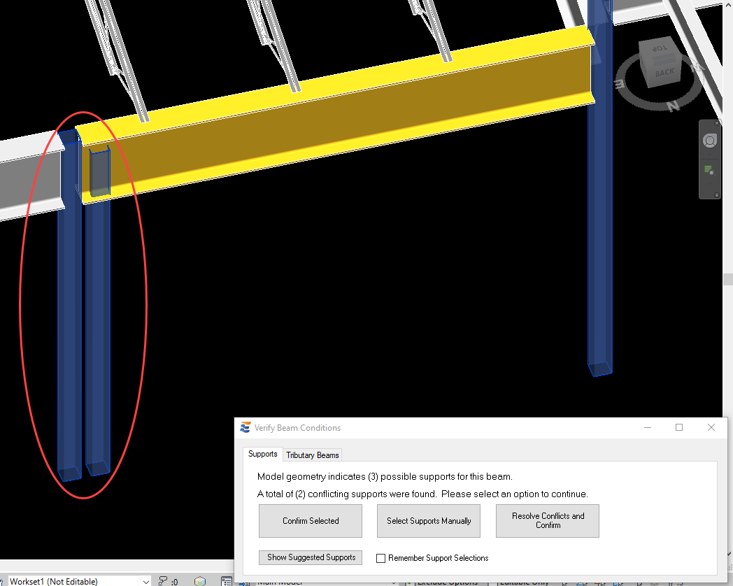
The proximity and geometry of the possible supports may not allow for a clear recommendation for one element or the other in all cases. If this occurs, the user will be notified in the approval form that a potentially conflicting support condition is found. For example, if two columns with nearly identical geometry are found very close to each other, the user will be presented with the option to “Confirm Selected”, “Select Supports Manually”, or “Resolve Conflicts”.
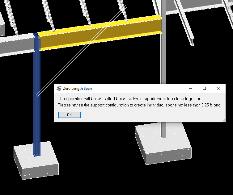
Users should be aware that proceeding via “Confirm Selected” or “Select Manually” may result in a downstream warning if the chosen supports are placed too close together. The minimum span length permitted is 0.25 ft. If any two support centers are more closely spaced, the calculation launch will be terminated with a warning, and the problematic supports will be indicated in the Revit view.
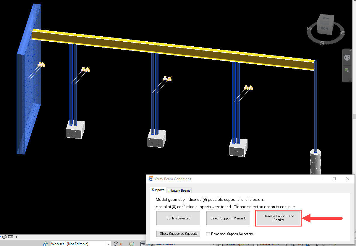
If the user opts to “Resolve…”, then the program will lead the user through a series of verifications for each location along the beam where conflicting supports are found. Clicking this button will take the user to the first location where supports conflict.
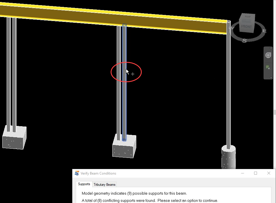
At each location, the conflicting supports will be automatically selected in the Revit view and a Revit multi-select process will begin. The Revit status bar (lower left corner of the main Revit window) indicates the number of conflicts found and gives instructions about how to proceed.

Moving the cursor over an element that is already selected will indicate the “-“ option to remove it from the selection.

Moving the cursor over an element that is not selected will indicate the “+” option to add it to the selection.
After manual selections have clarified the desired condition at the current conflict, clicking ”Finish” will cause the program to proceed directly to the next conflict. When all conflicts are resolved, the program will proceed to the next step of the calculation launch process.
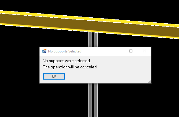
During the process of resolving conflicting supports, clicking “Cancel” on the Revit ribbon at any time to end a multi-select will terminate the calculation launch with a notification.
 <
<