Rectangular Beam Sections - Joined |
  
|
Rectangular Beam Sections - Joined |
|
Revit provides the ability for users to control whether or not adjacent physical elements are joined to each other. When they are joined, their solid geometries will be combined, rather than having two distinct geometries which overlap in 3D space and 2D views. Since the design behavior differs in joined vs. unjoined conditions, ENERCALC for Revit users should remain aware of the join relationships between concrete beams and concrete floors in a Revit model.
Instead of the approach described in the previous section (Rectangular Beam Sections - Unjoined), the user may alternatively choose to launch a rectangular beam calculation for a beam that IS JOINED to a slab in the Revit model.

When the calculation launch process reaches the "Section Geometry" tab, the user will be informed that the beam IS eligible for design as a T-Beam. Using the "Select" button on the row marked "Skip" and "No T-Beam" will launch the calculation as a rectangular beam without any Tee geometry:
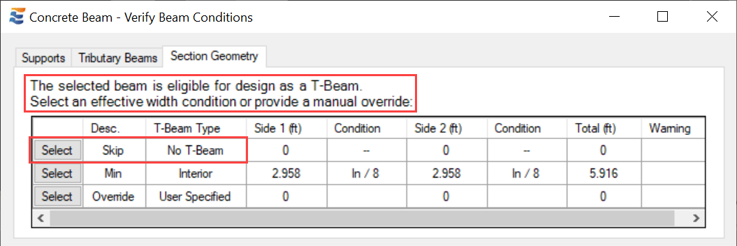
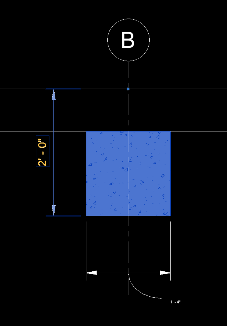
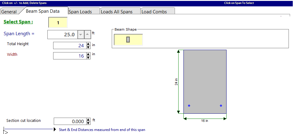
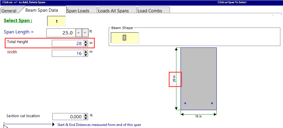
In doing so, the user will observe that the design calculation constructed in ENERCALC represents the gross combined depth of the beam AND the floor slab. No T-Beam flanges will be used.
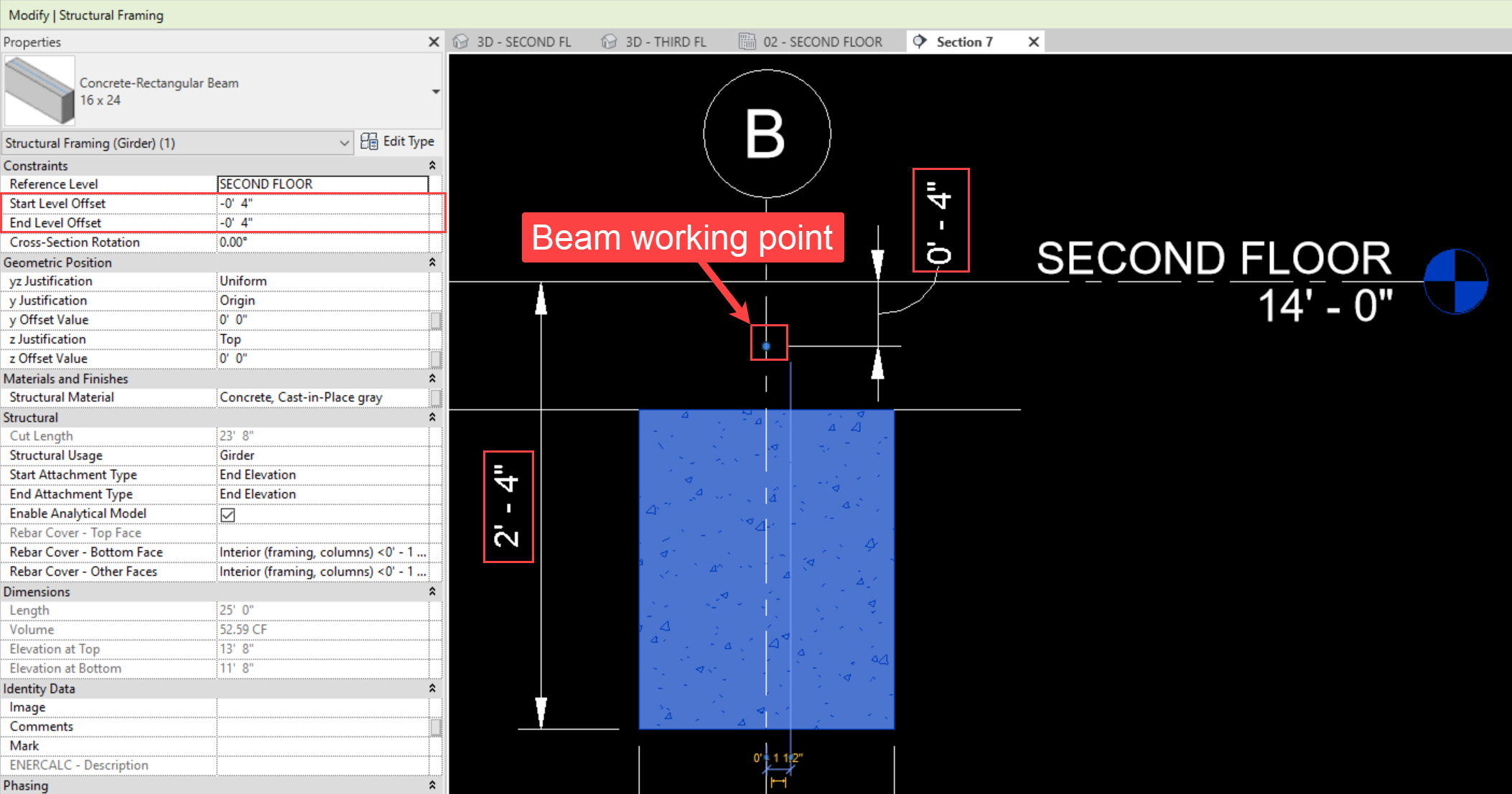
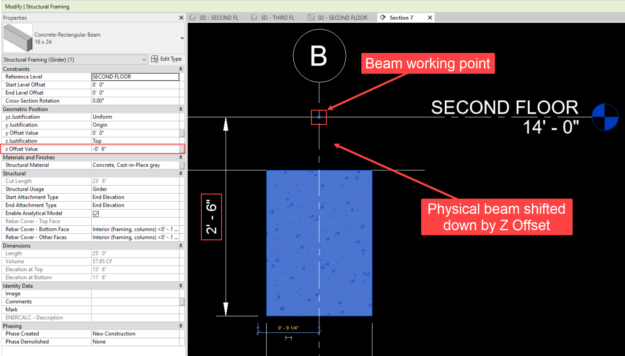
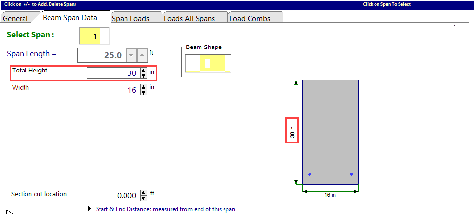
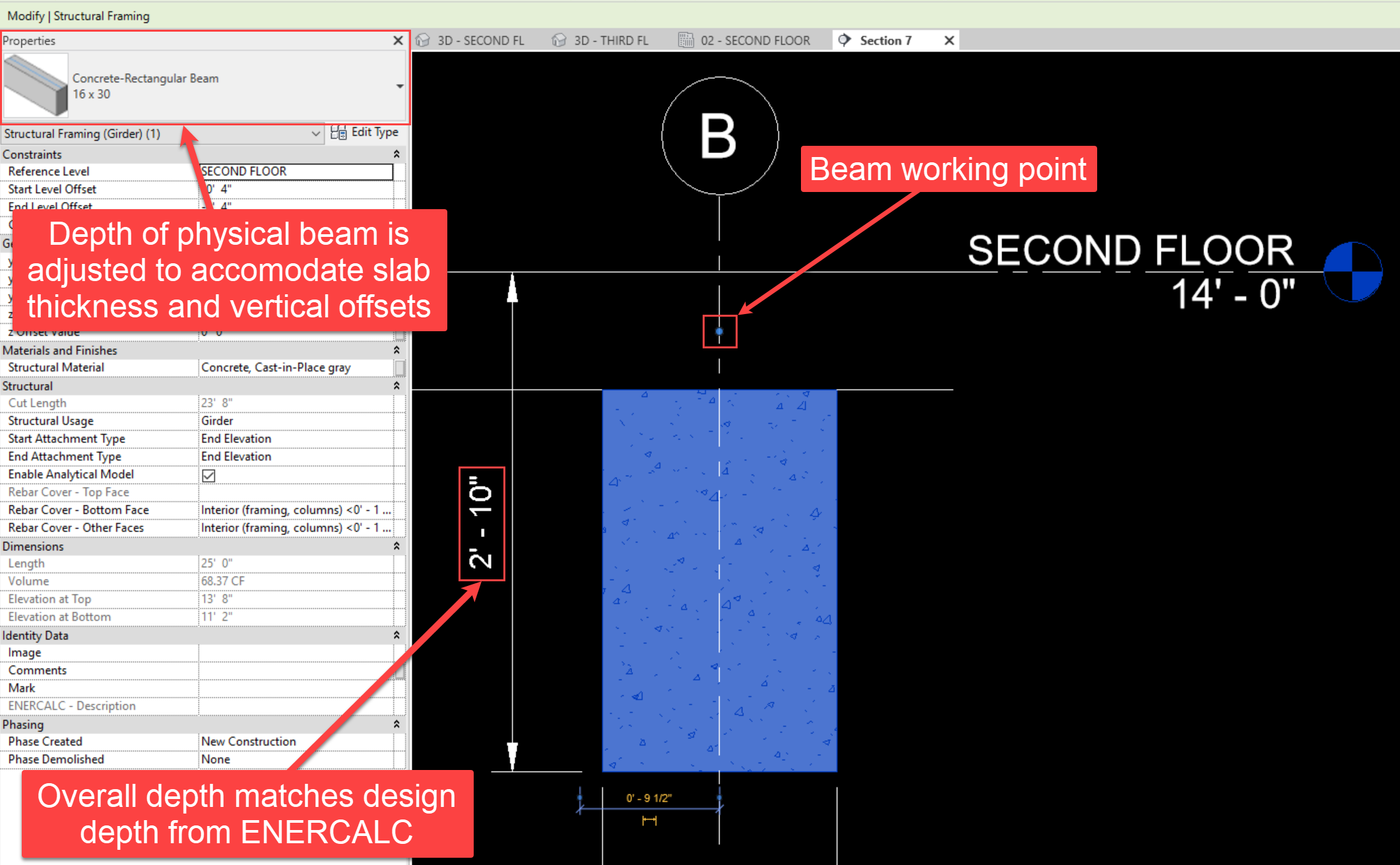
This relationship also holds true if the working point location of the beam is altered by physical movement or by adjustment of the "Start Level Offset" and "End Level Offset" parameters. Rather than matching the basic gross dimensions of the Revit beam element, the design dimensions displayed in ENERCALC will represent the combined geometry of the beam and the floor slab:
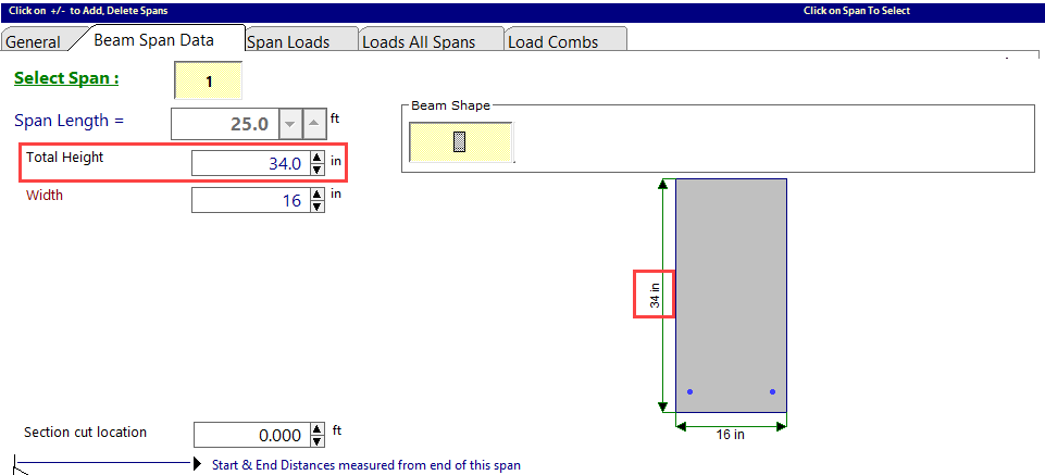
This relationship also holds true if the physical geometry of the beam is offset from its working point location by adjustment of the "Z Offset Value" parameter. Rather than matching the basic gross dimensions of the Revit beam element, the design dimensions displayed in ENERCALC will represent the combined geometry of the beam and the floor slab:
Once the design is satisfactory and the user clicks "Save and Close", the changes to the beam's design section size in ENERCALC will be automatically applied to the physical beam in the Revit model.
Note that the new dimensions applied to the Revit beam element are NOT the EXACT dimensions specified in the ENERCALC calculation. This is because the geometry of the joined slab is automatically considered when updating the size of the beam section. Instead, ENERCALC for Revit will assign a section geometry whose location and gross dimensions will combine with the thickness of the joined slab to create the overall geometry specified in the ENERCALC calculation:
 <
<