Torsional Analysis of Rigid Diaphragm Theory |
  
|
Torsional Analysis of Rigid Diaphragm Theory |
|
The distribution of lateral loads in structures with rigid diaphragms and orthogonal crosswalls or frame systems is a well-established topic in structural engineering literature. In such systems, the total lateral displacement of a resisting element results from the combined effects of flexural and shear deformations. This document presents a unified design method that captures these behaviors using energy-based principles and stiffness matrix computations.
This document also demonstrates a computational approach to distributing lateral forces in multi-resisting element systems, considering diaphragm rotation and translation, using stiffness matrices and energy principles to determine element forces and the overall center of rigidity.
For definitions of variables and symbols used throughout, refer to the Notations section at the end of this document.
Resisting Element Local Stiffness
We begin by characterizing how each resisting element displaces under load. These displacements are used to build the element's flexibility matrix, which can then be inverted to produce the element’s local stiffness matrix.
The lateral displacement of a resisting element results from both bending and shear deformation. The total displacement at the top of the element under a lateral load is expressed as , where is the displacement due to flexure, and is the displacement due to shear. These lateral displacements also depend on the end fixity conditions.
Displacement Behavior of Wall Elements
For both ends fixed (i.e., restrained against rotation):
Fixed-Fixed: (1)
For one end fixed and the other end pinned:
Fixed-Pinned: (2)
Where , the shear correction factor, is given by:
(3)
For walls with rectangular cross sections, is equal to 1.2.
NOTE: The shear modulus (sometimes also represented as ) of cementitious materials is often estimated as . This estimate is provided as a convenience in the module but may be overridden with a user-defined value.
For concrete, ACI 318 does not formally define , but it does present this as a reasonable approximation in Commentary R6.6.3.1
For masonry, TMS 402 includes the same approximation in Table 4.2.2.
Displacement Behavior of Bending Elements
For bending members, flexural deformation dominates the overall behavior, and shear effects can often be neglected. In these cases, displacement simplifies to the flexural component only:
Fixed-Fixed: (4)
Fixed-Pinned: (5)
Flexibility and Stiffness Matrices
Once the displacement is known for a unit load along each of the elements primary local axes, the flexibility matrix is formed:
(6)
Where:
= displacement along local 'x' in response to a unit force along local 'x'
= displacement along local 'y' in response to a unit force along local 'y'
due to decoupled behavior in orthogonal directions
To compute the local stiffness matrix, , we can simply invert . Since is diagonal, this inversion is straightforward:
(7)
NOTE: In some cases, users may choose to neglect stiffness along the element’s weak axis, typically when its contribution to lateral resistance is insignificant or unconservative to include. When doing so, the corresponding direction in the local stiffness matrix is assigned a value of zero, effectively removing its influence from the overall system stiffness.
Resisting Element Global Stiffness and Force Transformation
Resisting elements are often oriented at angles relative to the global axes. While each element’s local stiffness matrix accurately captures its resistance along its own principal axes, these stiffness properties must be expressed in the global coordinate system before they can be combined with other elements contributing to the overall lateral stiffness.
To accomplish this, a transformation matrix is applied to rotate stiffness values from the element’s local coordinate system into the global coordinate system. For a resisting element rotated by an angle (measured from the global x-axis to the element’s local x-axis), the rotation matrix is defined as:
(8)
NOTE: In this program, the rotation angle is typically defined as the angle from the global x-axis to the element’s local y-axis, since the local y-axis is generally aligned with the element’s strong axis. For example, a wall with a rotation of 0 degrees is parallel to the global x-axis, and a rotation of 90 degrees is parallel to the global y-axis. However, the rotation matrix used for stiffness transformation requires the angle to be measured from the global x-axis to the element’s local x-axis. Therefore, when using the program-defined angle, it is necessary to subtract 90 degrees to obtain the correct orientation for the transformation matrix.
The element global stiffness matrix is then obtained from the element local stiffness matrix through the following transformation:
(9)
After the rigid diaphragm analysis is complete and elemental forces in the global system have been determined, the same transformation matrix can also used to convert these forces back into the element’s local coordinate system to find the strong and weak axis applied shear. For example, given global forces , the corresponding local forces can be determined as:
(10)
Where:
Rigid Diaphragm Global Stiffness Matrix
We now turn to assembling the rigid diaphragm global stiffness matrix, which is formed by integrating the element global stiffness matrices into a single global stiffness matrix for the entire system.
Consider the displacements of the single wall assembly shown in Figure 1:
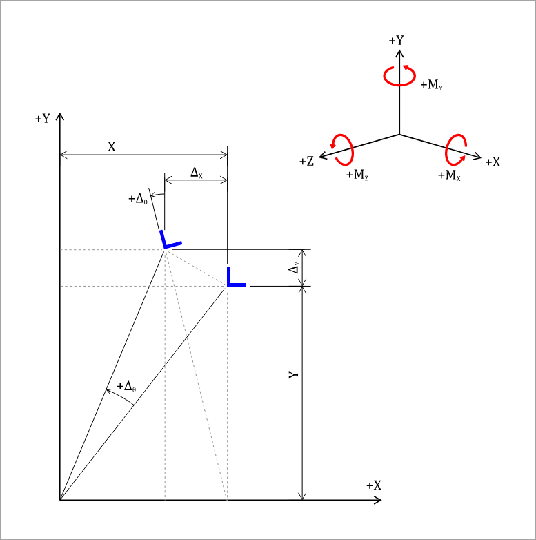
Figure 1: Element Rotation
The magnitude of the displacements are assumed to be very small. The assembly rotates through an angle (counter-clockwise positive) about the origin of coordinates X and Y, and translates and . The diaphragm is assumed to be very rigid compared to the walls. When the diaphragm rotates without translation, displacements occur which generate the following forces on the element:
(11)
(12)
(13)
(14)
Where:
is the force in the X direction due to a unit displacement in the Y direction.
is the rotational stiffness calculated as the moment about the Z axis due to a unit rotation of the element about the Z axis.
All values are plotted using the right-hand Cartesian coordinate axis system; thus a negative sign indicates a displacement in the negative direction or a clockwise moment. , , and are zero for this type of system.
Using small-angle approximations, it can be shown that for the displacement in Figure 1:
Thus, Equations 11, 12, and 14 can be revised as follows. It should also be noted that . Therefore, all subsequent formulations will adopt for consistency.
(15)
(16)
(17)
When the diaphragm translates without rotation (see Figure 2), displacements occur which generate the following forces on the element:
(18)
(19)
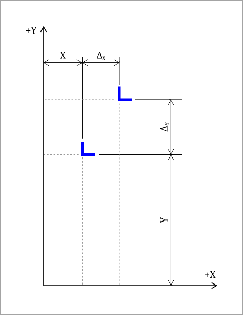
Figure 2: Element Translations
Equations 15 through 19 can then be combined to find the total element forces acting on the diaphragm when the diaphragm translates and rotates:
(20)
(21)
(22)
These equations may now be written in matrix notation:
(23)
If the applied loads on the diaphragm are and in the X and Y directions, and a torsional moment is also applied to the diaphragm in the positive, counter-clockwise direction:
(24)
(25)
(26)
Where:
is the sum of all resisting element forces acting in the global X direction.
is the sum of all resisting element forces acting in the global Y direction.
is the sum of the torsional moments from all resisting element forces acting about the diaphragm center of rigidity.
Substituting the values from Equations 24, 25, and 26 into Equations 20, 21, and 22 yields:
(27)
(28)
(29)
Again, these equations may now be written in matrix notation to describe the diaphragm's global force-displacement behavior:
(30)
To find the center of rigidity, the following relationships must be true:
(31)
(32)
Then, Equations 27, 28, and 29 become:
(33)
(34)
(35)
Where (36)
The solution for the center of rigidity as defined in Equation 31 and 32 can be found if any set of trial coordinates are taken with distances and to the center of rigidity. From Figure 3,
(37)
(38)
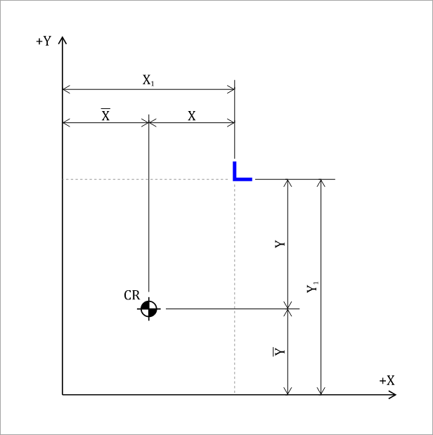
Figure 3: Center of Rigidity Trial Coordinates
Substituting Equations 37 and 38 into Equations 31 and 32:
(39)
(40)
By expanding and rearranging Equations 39 and 40, and noting that and (the coordinates of the center of rigidity) are constants, we obtain:
(41)
(42)
To solve this system of simultaneous equations for and , several approaches are possible. One common method is substitution, where one equation is rearranged to isolate a variable and then substituted into the other.
Equation 42 can be rearranged to express explicitly:
(43)
The resulting expression for can then be substituted into Equation 41, allowing the system to be solved explicitly for , as follows:
(44)
Final Solution
The solution for element global forces and and local shears and acting on any resisting element is then found as follows:
1.Compute the local and global stiffness matrices and for each element from Equations 7 and 9.
2.Locate the center of rigidity from Equations 43 and 44.
3.Assemble the rigid diaphragm global stiffness matrix and compute displacements from Equation 30.
4.Solve for element forces in the global system from Equation 23.
5.Transform the element global forces to local shears and from Equation 10.
Orthogonal Lateral Force Resisting Systems
For orthogonal lateral force resisting systems, the problem simplifies significantly. , and the preceding equations reduce to a standard set of equations which may be familiar from manual or spreadsheet-based rigid diaphragm analyses.
Equations 43 and 44 for the coordinates of the center of rigidity reduce to:
(45)
(46)
Similarly, Equation 30 for the diaphragm displacement simplifies to:
(47)
(48)
(49)
Finally, Equation 23 describing individual element forces acting on the diaphragm simplifies further, and substituting the results from Equations 47, 48, and 49 into this expression yields the final form of the solution.
(50)
(51)
A design approach was presented which allows for the distribution of lateral loads in structures with rigid diaphragms and crosswalls and/or frame systems of any orientation. Required stiffness coefficients were found by inverting the flexibility matrix of the lateral force resisting system. The analysis presented herein for a one-story structure can be easily extended to multi-level structure where the center of gravity and center of rigidity are the resultants of the centers of all the levels above the level of analysis.
For a detailed worked example using this approach, please see our Verification Example.
= Cross-sectional area
= Element local flexibility matrix
= Width of wall element
= Modulus of elasticity
= Shear modulus
= Force
= Force in the global 'x', 'y', or 'z' direction
= Element global force matrix
= Element local force matrix
= Element height
= Moment of inertia
= Minimum and maximum moment of inertia
= Moment of inertia about local 'x' or 'y' axis ()
= Moment of inertia about x-y axis ()
= Rotational stiffness
= Stiffness
= Element stiffness along local 'i' in response to a unit displacement along local 'j'
= Element global stiffness matrix
= Element local stiffness matrix
= Moment
= Torsional moment acting on resisting element
= Moment about the global 'x', 'y', or 'z' axis
= Applied lateral load
= Applied lateral load in the global 'x', 'y', or 'z' direction
= Statical moment of area above plane of desired shear flow
= Diaphragm torsional moment
= Rotation matrix
= Coordinate axes
= Distance from resisting element to center of rigidity
= Distance from resisting element to origin
= Distance from the center of rigidity to origin
= Shear correction factor for cross-sectional shape of the element
= Element total displacement
= Element displacement due to flexure
= Element displacement due to shear
= Element displacement along local 'i' in response to a unit force along local 'j'
= Displacement of the rigid diaphragm in the global 'x', 'y', or 'z' direction
= Angle of rotation of the rigid diaphragm about the center of rigidity
= Angle of rotation measured from the global x-axis to the element’s local x-axis
 <
<