Example 9: Scodelis-Lo Roof |
  
|
Example 9: Scodelis-Lo Roof |
|
Problem Description
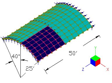
The Scodelis-Lo barrel roof [Ref. 4 pp3-20, Ref. 2] has a length of 50 ft, a radius of 25 ft, and a sweeping angle of 80 degrees. The roof is supported on rigid diaphragms along its two curved edges (Dx and Dy fixed, but not Dz). The two straight edges are free. A surface load of -90 lb/ft^2 in the global Y direction (self weight) is applied to the entire roof.
Material: E = 4.32e8 lb/ft^2 (3e6 psi); v = 0.0;
Thickness: t = 0.25 ft.
Find the maximum deflection and moments.
Suggested Modeling Steps
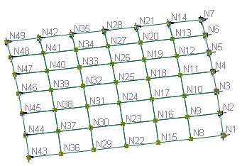
Due to the symmetry, only a quarter of the roof is modeled. A 6 x 6 mesh is used. The boundary conditions are specified in the following table.
Nodes |
Fixed DOFs |
N1 to N6 |
Z, OX, OY |
N7 |
X, Z, OX, OY, OZ |
N14, N21, N26, N35, N42 |
X, OY, OZ |
N43 to N48 |
X, Y, OZ |
N49 |
X, Y, OY, OZ |
▪Set proper units from Settings and Tools > Units & Precisions.
▪Generate members along an arc by Create > Templates > Arc Members. Enter a radius of 25, segments of 6, start angle 50, end angle 90.
▪Select all nodes and members, extrude members to shells by Modify > Extrude > Extrude Members to Shells. Enter a distance list of “6@4.1666” and direction of the global Z. Check both “Merge nodes and elements” and “Delete selected members after extrusion”.
▪Select all shell elements, define and assign the shell thickness properties by Modify > Shell Properties > Thicknesses. Make sure “Assign active thickness to currently selected shells” is checked in the dialog box.
▪Select the boundary nodes and apply proper supports as specified above by Create > Boundary Conditions > Support. You need to select and apply multiple times.
▪Select all shell elements, assign surface load by Create > Draw Loads > Surface Loads
▪Set the analysis options by Analysis > Analysis Options. Choose the model type “3D Frame & Shell”. Check or uncheck “Use Kirchhoff thin plate bending formulation for rectangular shells”. Check or uncheck “Use incompatible formulation for shell membrane actions or bricks”.
Results
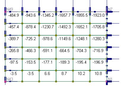
The comparison of displacements and moments between the program and the referenced results is excellent. Theoretical maximum vertical displacement is given by MacNeal & Harder [Ref. 4, pp3-20]. Other theoretical values are approximate readings (with different sign convention for moments) from graphs given by Zienkiewicz [Ref. 2 pp350-351]. The maximum Dy and Myy occur at the mid-point along the free edges. The maximum Mxx occurs at the center of the longitudinal middle section. The maximum Dz and Mxy occur at the corner points at supports.
Membrane |
Compatible |
Incompatible |
References |
||
Bending |
Kirchhoff |
MITC4 |
Kirchhoff |
MITC4 |
|
Displacement Vertical (in) |
-3.475 |
-3.489 |
-3.672 |
-3.687 |
-3.629 [Ref. 4] |
Displacement Longitudinal (in) |
0.1317 |
0.1317 |
0.1414 |
0.1414 |
app. 0.144 [Ref. 2] |
Mxx (ft-lb/ft) |
-1954 |
-1923 |
-2093 |
-2056 |
app. 2100 [Ref. 2] |
Myy (ft-lb/ft) |
636.0 |
633.9 |
667.9 |
666 |
app.-650 [Ref. 2] |
Mxy (ft-lb/ft) |
-1204 |
-1199 |
-1264 |
-1260 |
app. 1300 [Ref. 2] |
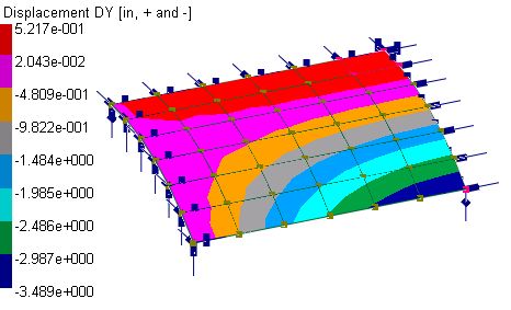
Displacement contour (MITC4-bending, compatible formulation)
 .
.
Mxx contour (MITC4-bending, compatible formulation)
Comments
The example is the de-facto standard test problem for shells due to the strong coupling of the bending and membrane actions. The problem is solved using the shell element with different membrane and bending formulations from which excellent results are obtained. The incompatible membrane formulation yields results closer to the referenced values.
The use of symmetry saves computing time and memory, but requires careful thinking with regard to the boundary conditions. You may model the entire roof by simply fixing Dx, Dy along the curved edges and Dz at the longitudinal central section.
