Example 8: Brick Patch Test |
  
|
Example 8: Brick Patch Test |
|
Problem Description
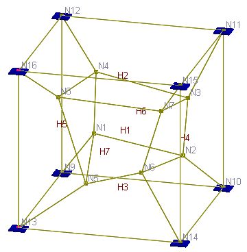
This is a patch test for a unit cube [Ref. 4 pp3-20]. The cube is modeled with 7 eight-node brick elements. Nodal coordinates, element connectivity and boundary conditions are given in the following tables. Boundary conditions are given as forced displacements. No additional loads are prescribed.
Material: E = 1.e6 psi; ν = 0.25
Find stresses for each element.
Nodal coordinates (inch)
|
Displacement field u = 0.001 * (2x + y + z) / 2 v = 0.001 * (x + 2y + z) / 2 w = 0.001 * (x + y + 2z) / 2 Forced displacements (inch) on boundary
All strains are constant. For example
|
Element Connectivity
Element |
Node1 |
Node2 |
Node3 |
Node4 |
Node5 |
Node6 |
Node7 |
Node8 |
1 |
1 |
2 |
3 |
4 |
5 |
6 |
7 |
8 |
2 |
4 |
3 |
11 |
12 |
8 |
7 |
15 |
16 |
3 |
9 |
10 |
2 |
1 |
13 |
14 |
6 |
5 |
4 |
2 |
10 |
11 |
3 |
6 |
14 |
15 |
7 |
5 |
9 |
1 |
4 |
12 |
13 |
5 |
8 |
16 |
6 |
9 |
10 |
11 |
12 |
1 |
2 |
3 |
4 |
7 |
5 |
6 |
7 |
8 |
13 |
14 |
15 |
16 |
Suggested Modeling Steps
▪Set proper units from Settings and Tools > Units & Precisions.
▪Input the nodal coordinates by Tables > Nodes.
▪Modify the default material by Tables > Materials.
▪Input the bricks by Tables > Bricks. Use the default material (=1).
▪Input the boundary conditions by Tables > Supports. Enter the support flag “111000” for each support. Enter the forced displacements according to the table above.
▪Set the analysis options by Analysis > Analysis Options. Choose the model type “3D Brick”.
Results
The comparison of stresses (psi) between the program and the referenced results is excellent. Each stress component is uniform in all seven elements.
|
Sxx |
Syy |
Szz |
Sxy |
Syz |
Sxz |
ENERCALC 3D |
1999.982 |
1999.982 |
1999.982 |
399.999 |
399.999 |
399.999 |
[Ref. 4] |
2000 |
2000 |
2000 |
400 |
400 |
400 |
Comments
The brick element passes the patch test. Therefore, “the results for any problem solved with the element will converge toward the correct solution as the elements are subdivided.” [Ref. 4] The tiny differences in stresses are due to the penalty approach employed in support enforcement.
