Example 10: A Shear Wall |
  
|
Example 10: A Shear Wall |
|
Problem Description
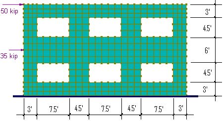
A two-story concrete shear wall is subjected to two horizontal point forces at the floor levels. The wall is 37.5 ft long and 21 ft high, with six openings of 7.5 x 4.5 ft.
Material: E = 4e6 psi; ν = 0.15
Thicknesses: t = 12 inch.
Suggested Modeling Steps
▪Set proper units from Settings and Tools > Units & Precisions.
▪Generate the plate by Create > Templates > Rectangular Shells. Enter a distance list of “3@1, 21@1.5, 3@1” for the X direction and a distance list of “3@1, 10@1.5, 3@1” for the Y direction.
▪Select the middle eight nodes at each opening and delete them. The shells that are connected to these nodes are deleted automatically.
▪Select all shell elements, define and assign material properties by Modify > Shell Properties > Materials. Make sure “Assign active material to currently selected elements” is checked in the dialog box.
▪Select all shell elements, define and assign the shell thickness properties by Modify > Shell Properties > Thicknesses. Make sure “Assign active thickness to currently selected shells” is checked in the dialog box.
▪Press ESC key to unselect all. Select the nodes at the bottom and assign them fixed supports.
▪Select the two nodes at each story level and assign them nodal loads by Create > Draw Loads > Nodal Loads.
▪Set the analysis options by Analysis > Analysis Options. Choose the model type “2D Plane Stress”. Check “Use incompatible formulation for shell membrane actions or bricks”.
Results
No comparison of results is available. Displacement Dx contour and Stress Syy contour is provided in the following.
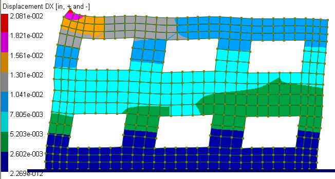
Displacement Dx contour on deflected shape
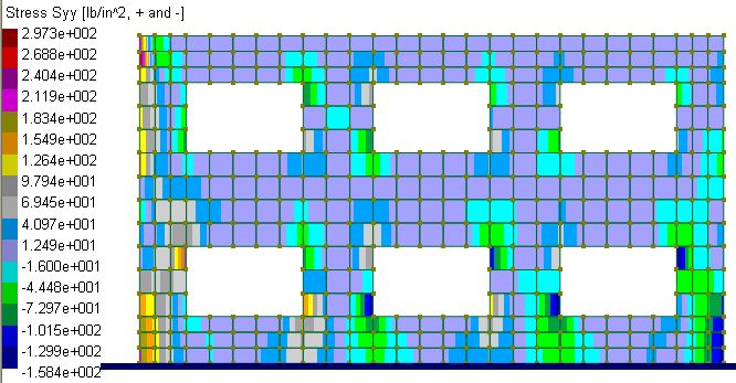
Stress Syy contour
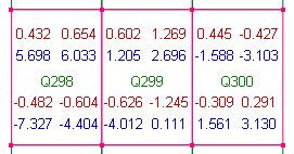
To verify the results, the horizontal shear is checked at the middle elevation of the second story openings. The following table shows the “Membrane nodal resultants” of four piers by View > Display Options (annotation mode = “Annotate selected entities” to avoid congestion of texts). You may also view the same nodal resultants in a spreadsheet by Analysis Results > Shell Forces, Moments & Stresses > Shell Nodal Resultants. You can then copy and paste selected data to your preferred spreadsheet program to perform summation or other computations. It is important to point out that nodal resultants are expressed in the element local coordinate systems.
Pier 1
ΣFx = 0.432 + 0.654 + 0.602 + 1.269 + 0.445 - 0.427 = 2.975 kips |
|
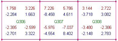
Pier 2
ΣFx = 1.758 + 3.226 + 7.226 + 5.786 + 3.144 + 2.722 = 23.862 kips
|
|
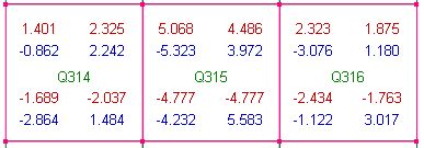
Pier 3
ΣFx = 1.401 + 2.325 + 5.068 + 4.486 + 2.323 + 1.875 = 17.478 kips
|
|
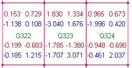
Pier 4
ΣFx =
0.153 + 0.729 + 1.83 + 1.334 + 0.965 + 0.673 = 5.684 kips
|
|
All Piers ΣFx = 2.975 + 23.862 + 17.478 + 5.684 = 49.999 (app.= 50 kips) |
|
Membrane nodal resultants of four piers at the middle elevation of the second story
Comments
The example problem shows how to perform structural analysis on a shear wall. Although no comparison of results is available, we demonstrate the reliability of the program by checking the horizontal shear.
In designing concrete sections, we generally need forces and moments instead of stresses. We may acquire axial forces and moments in the same manner as in shears. For example, to determine the moment at the second pier above, we may sum the moments by nodal resultants Fy about the center of the pier.
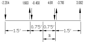
Fyi (kips) |
Xi (ft) |
Fyi * Xi (ft-kips) |
-2.284 |
-2.25 |
5.139 |
1.663 |
-0.75 |
-1.24725 |
-8.458 |
-0.75 |
6.3435 |
4.611 |
0.75 |
3.45825 |
-3.718 |
0.75 |
-2.7885 |
3.082 |
2.25 |
6.9345 |
ΣFy = -5.104
|
|
sum = 17.8395 |
Internal Forces and Moment at middle of the second pier
Axial Force = -5.104 kips
Shear Force = 23.862 kips
Moment = 17.8395 ft-kips
You are encouraged to model this wall with members and compare the results with those in this example. Care should be exercised in segmenting the members and assigning them appropriate section properties. Since the sections of the members are relatively deep, shear deformations must be considered.