Example 6: Circular Plate On Grade |
  
|
Example 6: Circular Plate On Grade |
|
Problem Description
A circular steel plate with a thickness of 0.2 inch and a diameter of 20 inches is simply supported along its edge [Ref. 6 pp326-327 & pp 380-381]. The plate is loaded with a uniform load of 3 lb/in2.
Material: E = 3e7 psi; ν = 0.285
Thicknesses: t = 0.2 inch.
Determine the deflection and moment at the center for the following two cases:
a). No elastic foundation.
b). An elastic foundation with a modulus of 20 lb/in3.
Suggested Modeling Steps
▪Set proper units from Settings and Tools > Units & Precisions.
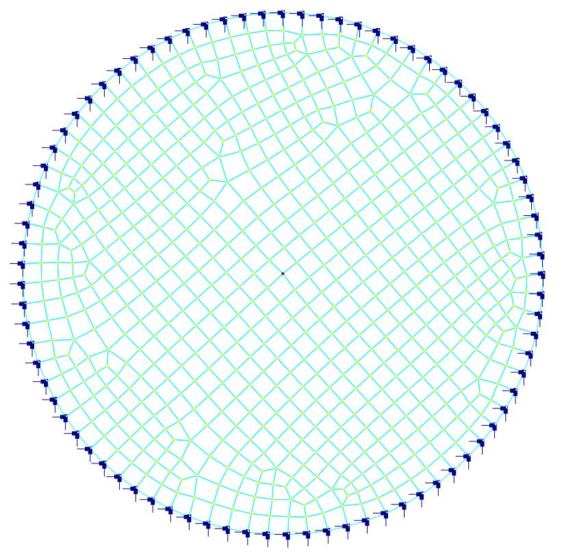
▪Generate the circular plate by Create > Templates > Circular Shells. Enter a radius of 10 and segments of 80. Select “Pinned” supports along the edge.
▪Select all shell elements, define and assign material properties by Modify > Shell Properties > Materials. Make sure “Assign active material to currently selected elements ” is checked in the dialog box.
▪Select all plate elements, define and assign the shell thickness properties by Modify > Shell Properties > Thicknesses. Make sure “Assign active thickness to currently selected shells” is checked in the dialog box.
▪Select all shell elements, assign them the surface load by Create > Draw Loads > Surface Loads.
▪For case b) only, Select all shell elements, assign them surface springs by Create > Boundary Conditions > Springs.
▪Set the analysis options by Analysis > Analysis Options. Choose the model type “2D Plate Bending”. Uncheck “Use Kirchhoff thin plate bending formulation for rectangular shells”.
Results
The comparison of deflections and moments (absolute values) at the center of each plate between the program and the referenced results is excellent. Moments are the same in all directions at the center.
|
@ center |
ENERCALC 3D |
[Ref. 6] |
Case a without elastic foundation |
Deflection (in) |
0.089 |
0.0883 |
Moment (in-lb/in) |
61.54 |
61.5 |
|
Case b with elastic foundation |
Deflection (in) |
0.064 |
0.0637 |
Moment (in-lb/in) |
43.21 |
43.3 |
Comments
This example problem tests the reliability of the MITC4 plate bending element. It also shows how surface springs may be used to model an elastic (Winkler) foundation. Two separate models are used for case a) and case b). The generated shell elements are mostly rectangular. Some non-rectangular shell elements exist along the edge.
A relatively fine mesh is employed in order to minimize the discretization error along the edge. The default MITC4 thick plate element is used. It is important to point out that Kirchhoff thin plate elements should not be used here due to the existence of non-rectangular elements.
