Example 5: Rectangular Plate |
  
|
Example 5: Rectangular Plate |
|
Problem Description
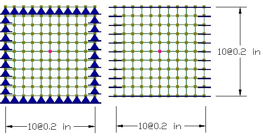
Two 2 x 2 inch square plates [Ref. 4, pp3-20] are clamped and simply supported along their edges respectively. Each plate is loaded with two sets of loads in two different load cases. The first set load is a point load applied at the center of the plate. The second set load is a uniform pressure applied to the entire plate. Use a 10x10 mesh.
Material: E = 1.7472e7 psi; ν = 0.3
Thicknesses: t = 1.0e-4 inch.
Point load P = 4e-4 lb
Uniform pressure p = 1e-4 lb/in^2
Determine the deflections at the center of plates, using both the thin Kirchhoff and the thick MITC4 plate formulations.
Suggested Modeling Steps
▪Set proper units from Settings and Tools > Units & Precisions.
▪Generate the first plate by Create > Templates > Rectangular Shells. Enter a distance list of “10@0.2” for the X direction and a distance list of “10@0.2” for the Y direction.
▪Select all shell elements generated and copy them to a new location by Modify > Copy. Enter valid copy distances so the new plates will not overlap with the existing shells. For example, DeltaX=3, DeltaY=0, and DeltaZ = 0.
▪Select all shell elements, define and assign material properties by Modify > Shell Properties > Materials. Make sure “Assign active material to currently selected elements” is checked in the dialog box.
▪Select all shell elements, define and assign the shell thickness properties by Modify > Shell Properties > Thicknesses. Make sure “Assign active thickness to currently selected shells” is checked in the dialog box.
▪Press ESC key to unselect all. Select the nodes along all edges of the first plate model and assign them pinned supports by Create > Boundary Conditions > Support. Select the nodes along all edges of the second plate model and assign them fixed supports by Create > Boundary Conditions > Support.
▪Define two load cases named “Point” and “Uniform”.
▪Define two load combinations. In the first load combination, set the load factor of 1.0 for load case “Point” and 0s for other load cases. In the second load combination, set the load factor of 1.0 for load case “Uniform” and 0s for other load cases.
▪Select center nodes of the two plate models, assign them the point loads of load case “Point” by Create > Draw Loads > Nodal Loads.
▪Select all shell elements, assign them the uniform loads of case “Uniform” by Create > Draw Loads > Surface Loads.
▪Set the analysis options by Analysis > Analysis Options. Choose the model type “2D Plate Bending”. Check or uncheck “Use Kirchhoff thin plate bending formulation for rectangular shells”.
Results
The comparison of the deflections (inches) at the center of each plate between the program and the referenced results is excellent.
Boundary |
Loading |
ENERCALC 3D |
[Ref. 4] |
|
MITC4 |
Kirchhoff |
|||
Simple |
Point |
11.555 |
11.762 |
11.60 |
Uniform |
4.049 |
4.044 |
4.062 |
|
Clamped |
Point |
5.475 |
5.750 |
5.60 |
Uniform |
1.256 |
1.29 |
1.26 |
|
Comments
This is one of the standard test problems proposed to test the effectiveness of plate elements in bending [Ref. 4]. Closed form solutions exist for both plates under point and uniform loading [Ref. 5, 6]. The problem is solved using both thick (MITC4) and thin (Kirchhoff) plate bending formulations. The results from both formulations are very close and compared well with those given by the reference.
It is important to point out that the MITC4 thick plate element can be used to model both a thick plate where shear deformation may be significant and a thin plate where shear deformation is negligible. When it is used to model a very thin plate as in this example, the MITC4 produces results close to those produced by the Kirchhoff thin plate element. The MITC4 plate element is free from shear locking, and is insensitive to distortion of element geometry. It is arguably the best plate bending element currently available.
