Example 4: A Portal Frame With P-Delta |
  
|
Example 4: A Portal Frame With P-Delta |
|
Problem Description
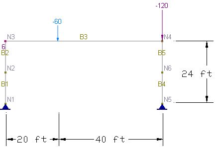
The following portal frame [Ref. 7, pp252] has a span of 60 ft and a column height of 24 ft. The beam is vertically loaded with 60 kips placed at 20 ft from the left end of the beam. The right column is vertically loaded with 120 kips. A horizontal load of 6 kips is applied at the joint of the beam and the left column. Each column is modeled with 2 members. The beam is modeled with a single frame element.
Columns: W10x45, A = 13.3 in2, Iz = 248 in4
Beam: W27x84, A = 24.8 in2, Iz = 2850 in4
Material: E = 2.9e7 psi, ν = 0.3
Perform analysis for the following two cases:
a). First order (Linear) elastic analysis
b). Second order (P-Delta) elastic analysis
Suggested Modeling Steps
▪Set proper units from Settings and Tools > Units & Precisions.
▪Generate the 2D frame by Create > Templates > Rectangular Frames. Enter a distance list of “60” for the X direction and a distance list of “24” for the Y direction. Do not enter anything for the Z direction. Select “Pinned” supports at the bottom of the dialog.
▪Select the lower horizontal beam generated and delete it by Modify > Delete.
▪Select the two columns and split each into 2 members by Modify > Split > Split Members.
▪Select all members, define and assign the material properties by Modify > Member Properties > Materials. Make sure “Assign active material to currently selected elements” is checked in the dialog box.
▪Select the four columns, define and assign the column section properties by Modify > Member Properties > Sections. Make sure “Assign active section to currently selected members” is checked in the dialog box.
▪Select the horizontal beam, define and assign the member section properties by Modify > Member Properties > Sections. Make sure “Assign active section to currently selected members” is checked in the dialog box.
▪Assign the nodal loads and point loads of “Default” load case by Create > Draw Loads > Nodal Loads, Point Loads. Make sure you select the nodes or member beforehand.
▪Create two load combinations by Create > Load Combinations. Set a load factor of 1.0 for the “Default” load case for each combination. Set the second combination to perform the P-Delta analysis.
▪Set the analysis options by Analysis > Analysis Options. Choose the model type “2D Frame”. Uncheck “Consider shear deformation on members”.
Results
The comparison between the program and the referenced results is good.
|
|
ENERCALC 3D |
[Ref. 7] |
Linear |
Maximum Displacement (in) |
4.387 |
4.4 |
Max + moment in beam (in-kips) |
8707.7 |
8708 |
|
Max – moment in beam (in-kips) |
2044.3 |
2044 |
|
P-Delta |
Maximum Displacement (in) |
8.26 |
8.1 |
Max + moment in beam (in-kips) |
9079.4 |
9078 |
|
Max – moment in beam (in-kips) |
2663.3 |
2661 |
Comments
The portal frame is analyzed by first order and second order elastic methods. Significant stress stiffening effect is observed. Although each physical column is modeled by 2 members, the program accounts for the P-Delta (P-Δ) effect very well even without splitting columns. However, you must split each column into more segments to account for p-delta (P-δ) effect. The same is also true when buckling analysis is desired.
The program does not perform buckling analysis directly. You may estimate the buckling load through trial-and-error with different load factors in the P-Delta load combination. The buckling load factor (λ) given by the reference [Ref. 7] is 2.2.
