Example 3: Linear and Non-linear Nodal Springs |
  
|
Example 3: Linear and Non-linear Nodal Springs |
|
Problem Description
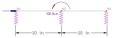
A 2-span continuous beam is supported by three springs. Each span is 10 inches long.
A concentrated moment M = 100 lb-in is applied at the middle spring.
Default material and section properties in the program are used.
Spring constants: Ky = 10 lb/in
The left and middle springs are linear.
Analyze the model for the following two cases.
a). The right spring is linear
b). The right spring is compression only
Suggested Modeling Steps
▪Set proper units from Settings and Tools > Units & Precisions.
▪Input nodal coordinates for Nodes 1, 2, 3 by Tables > Nodes
▪Input the two members by Tables > Members. Use default material (=1), section (=1), and local angle (=0) for both members.
▪Input the three nodal springs by Tables > Springs > Nodal Springs. Spring flags for the left and middle springs are “000000”. Spring flag for the right spring is “000000” for case a) and “010000” for case b). Enter the spring constant Ky = 10 for all springs.
▪Input a support at the N1 by Tables > Supports. The support has the flag of “100000” and 0s for all forced displacements.
▪Input the nodal moment for N2 by Tables > Nodal Loads. Enter “5” for the load direction (OZ) and “100” for the load value.
▪Set the analysis options by Analysis > Analysis Options. Choose the model type “2D Frame”. Set the maximum nonlinear iterations to be “10”.
Results
In case a), a force couple is developed in the left and right springs. The middle spring has a zero force. Fcouple = M / (20 in) = 5 lb. Δ3y = Fcouple / Ky = 0.5 in.
In case b), a force couple is developed in the left and middle springs. The right spring is eliminated because it is compression-only and a positive displacement occurs at N3. Fcouple = M / (10 in) = 10 lb. Δ2y = Fcouple / Ky = 1 in.
Displacements and spring reactions from ENERCALC 3D are shown in the following table. They are identical to the theoretical results.
|
Displacements (in) |
Spring reactions (lb) |
||||
|
N1 |
N2 |
N3 |
N1 |
N2 |
N3 |
Case a |
-0.5 |
0 |
0.5 |
5 |
0 |
-5 |
Case b |
-1 |
1 |
3 |
10 |
-10 |
0 |
Comments
The problem is linear for case a) and nonlinear for case b). The program performs 3 iterations for case b). The first iteration includes all three springs. The second iteration eliminates the compression spring. The third iteration checks for convergence.
This is a very simple problem that involves nodal springs only. More complicated problems may be solved just as easily. The program supports line and surface springs that may be applied to members and shells. Line springs may be used in modeling beams on grade and surface springs may be used in modeling mat (Winkler) foundations. Both line and surface springs may be linear or nonlinear (compression-only or tension only).
Default material and section properties are used because they do not affect the results in the example.
