Example 2: A Truss |
  
|
Example 2: A Truss |
|
Problem Description
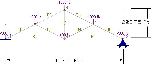
A truss with a span of 30 ft and a height of 7.5 ft is loaded with six concentrated loads at joints [Ref. 9, pp355].
Default material and section properties in the program are used.
Determine the axial forces of the truss members and the support reactions
Suggested Modeling Steps
▪Set proper units from Settings and Tools > Units & Precisions.
▪Generate the drawing grid by Create > Grids & Snaps > Drawing Grid Setup. Enter a distance list of “4@7.5” for the X direction and a distance list of “2@3.75” for the Y direction.
▪Draw the truss members by Create > Members. Point to the intersections of the drawing grid and left-click the mouse from point to point. The drawing action is continuous. Right click the mouse to start drawing from a new location.
▪Assign the nodal loads to the joints by Create > Draw Loads > Nodal Loads.
▪Set the analysis options by Analysis > Analysis Options. Choose the model type “2D Truss”.
Results
The comparison between the program and the referenced results is excellent.
|
ENERCALC 3D |
[Ref. 9] |
Chord B1 – Axial force (kips) |
4.44 |
4.44 |
Chord B8 – Axial force (kips) |
-4.964 |
-4.96 |
Support Reaction (kips) |
3.12 |
3.12 |
Comments
No displacements are given in the reference and therefore not compared. Default material and section properties are used because the truss is determinant and the displacements are not desired.
