E-04 (Brick Patch Test) |
  
|
E-04 (Brick Patch Test) |
|
Problem Description
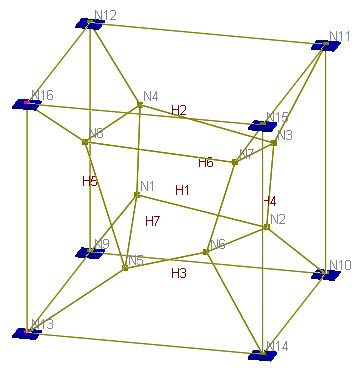
This is a patch test for a unit cube [Ref 1]. The cube is modeled with 7 eight-node brick elements. Nodal coordinates, element connectivity, and boundary conditions are given in the following tables. Boundary conditions are given as forced displacements. No additional loads are prescribed.
Material: E = 1.e6 psi; ν = 0.25
Find stresses for each element.
Nodal coordinates (inch)
|
Displacement field u = 0.001 * (2x + y + z) / 2 v = 0.001 * (x + 2y + z) / 2 w = 0.001 * (x + y + 2z) / 2 Forced displacements (inch) on boundary
All strains are constant. For example
|
Element Connectivity
Element |
Node1 |
Node2 |
Node3 |
Node4 |
Node5 |
Node6 |
Node7 |
Node8 |
1 |
1 |
2 |
3 |
4 |
5 |
6 |
7 |
8 |
2 |
4 |
3 |
11 |
12 |
8 |
7 |
15 |
16 |
3 |
9 |
10 |
2 |
1 |
13 |
14 |
6 |
5 |
4 |
2 |
10 |
11 |
3 |
6 |
14 |
15 |
7 |
5 |
9 |
1 |
4 |
12 |
13 |
5 |
8 |
16 |
6 |
9 |
10 |
11 |
12 |
1 |
2 |
3 |
4 |
7 |
5 |
6 |
7 |
8 |
13 |
14 |
15 |
16 |
Results
The displacements of internal nodes can be calculated based on the boundary conditions. The constant stresses are also given by [Ref 1].
Units: displacement – in
Nodes |
ENERCALC 3D (compatible and incompatible) |
Theoretical |
||||
Dx |
Dy |
Dz |
Dx |
Dy |
Dz |
|
1 |
5.16E-04 |
5.63E-04 |
4.88E-04 |
5.16E-04 |
5.63E-04 |
4.88E-04 |
2 |
1.11E-03 |
8.45E-04 |
8.45E-04 |
1.11E-03 |
8.45E-04 |
8.45E-04 |
3 |
1.31E-03 |
1.21E-03 |
1.01E-03 |
1.31E-03 |
1.21E-03 |
1.01E-03 |
4 |
7.63E-04 |
1.00E-03 |
7.42E-04 |
7.63E-04 |
1.00E-03 |
7.42E-04 |
5 |
7.35E-04 |
6.68E-04 |
8.96E-04 |
7.35E-04 |
6.68E-04 |
8.96E-04 |
6 |
1.17E-03 |
9.85E-04 |
1.17E-03 |
1.17E-03 |
9.85E-04 |
1.17E-03 |
7 |
1.46E-03 |
1.41E-03 |
1.38E-03 |
1.46E-03 |
1.41E-03 |
1.38E-03 |
8 |
8.89E-04 |
1.18E-03 |
1.16E-03 |
8.89E-04 |
1.18E-03 |
1.16E-03 |
Units: stress - psi
|
Sxx |
Syy |
Szz |
Sxy |
Syz |
Sxz |
ENERCALC 3D (compatible) |
1999.982 |
1999.982 |
1999.982 |
399.999 |
399.999 |
399.999 |
ENERCALC 3D (incompatible) |
1999.978 |
1999.978 |
1999.978 |
399.998 |
399.998 |
399.998 |
[Ref. 1] |
2000 |
2000 |
2000 |
400 |
400 |
400 |
Comments
Both compatible and incompatible brick elements pass the patch test. Therefore, “the results for any problem solved with the element will converge toward the correct solution as the elements are subdivided.” [Ref. 1] The tiny differences in stresses are due to the penalty approach employed in support enforcement during solution.
Reference
[1]. MacNeal & Harder, “A Proposed Standard Set of Problems to Test Finite Element Accuracy”, Finite Elements in Analysis and Design, 1 (1985) 3-20
