E-03 (Incompatible Brick) |
  
|
E-03 (Incompatible Brick) |
|
Objective
To verify the behavior of incompatible brick formulations using irregular meshes
Problem Description
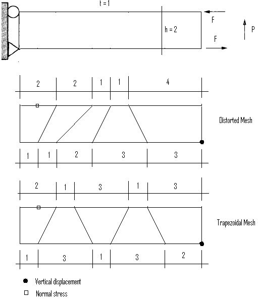
A straight beam with distorted and trapezoidal elements is subjected to two sets of loading: a). end moments; b). end shear.
Material properties: E = 1500 psi, ν = 0.25
Geometric properties: L = 10 in, h = 2 in, t = 1 in
Loads: a). F = 1000 lb; b). P = 300 lb
Finite Element Model
5 brick (incompatible) elements
Model type: 3D Brick
Results
The displacements and stresses are given by [Ref 1]. The stresses given for ENERCALC 3D below are the average values at the top four nodes of each of the elements at the supports.
Unit: displacement – in; stress - psi
Mesh |
Loading |
ENERCALC 3D |
Ref 1 (Theoretical) |
||
Displacements @ tip |
Stresses @ root |
Displacements @ tip |
Stresses @ root |
||
Distorted |
Moment |
95.80 |
-2471 |
95.8 (100) |
-3015 (3000) |
Shear |
97.90 |
-3223 |
97.9 (102.6) |
-4138.5 (-4050) |
|
Trapezoidal
|
Moment |
76.27 |
-2503 |
76.252 (100) |
-2883.5 (3000) |
Shear |
80.16 |
-3309 |
80.115 (102.6) |
-3860 (-4050) |
|
Comments
The displacements given by ENERCALC 3D are almost identical to the referenced values. The stresses are calculated by averaging the top four nodes of each element at the root. The stresses given by ENERCALC 3D are different from the referenced values due to different methods used in stress calculation. The correct theoretical displacements and stresses are given in parenthesis in the table.
Reference
[1]. Wilson, Ibrahimbegovic, “Use of incompatible displacement modes for the calculation of element stiffness or stresses”, Finite Elements in Analysis and Design 7 (1990) 229-241
