E-05 (Hemispherical Shell with Point Loads) |
  
|
E-05 (Hemispherical Shell with Point Loads) |
|
Objective
To verify the behavior of the incompatible brick element in a doubly-curved, very thin shell structure
Problem Description
This problem is the same as problem D-05. Only this time we are using the 3D brick element instead of the MITC4 shell element to model the structure.
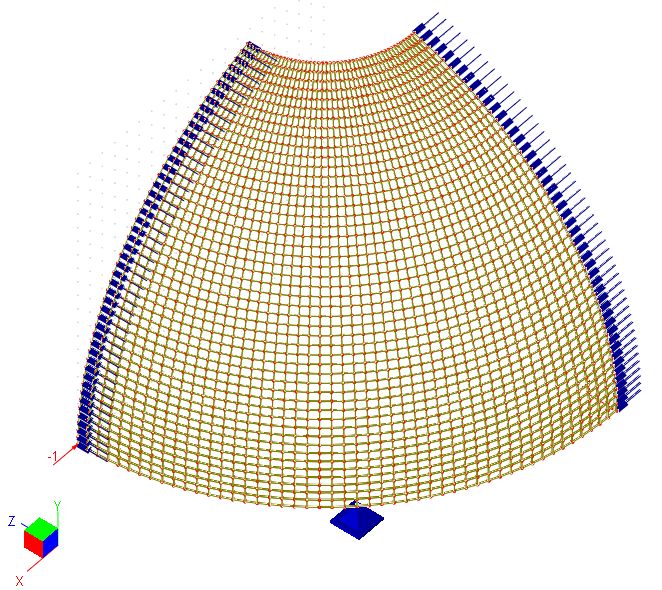
Finite Element Model
48 x 48 x 1 incompatible brick elements
Due to symmetry of the structure, we model only a quadrant of the structure. Restraints in the direction of global X and Z are applied to the quadrant lines respectively. A single vertical restraint is applied at the center of the quadrant equator. This is to prevent instability of the structure.
Model type: 3D Brick
Results
The result given by ENERCALC 3D compares well with benchmark values.
Units: displacement – ft
Radial displacement at load point
|
48 x 48 x 1 mesh |
Incompatible brick element |
9.262e-2 |
Benchmark Value |
9.400e-2 |
Comments
The result given by ENERCALC 3D is comparable to the benchmark value.
This problem is one of the more challenging benchmark tests for solid elements. The reason is that the shell is doubly curved and shell thickness is very small in comparison with its span (radius). We used a relatively fine mesh so the element aspect ratio (8:7:1) would not be too large. Also, we used incompatible brick element formulation. Compatible brick element formulation would be too stiff for this mesh model.
Modeling Tips
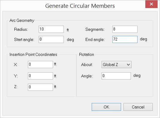
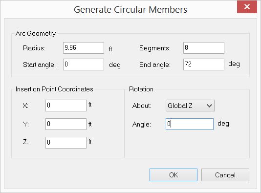
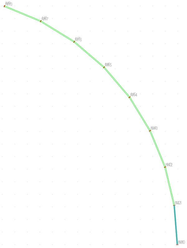
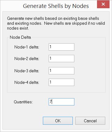
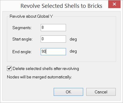
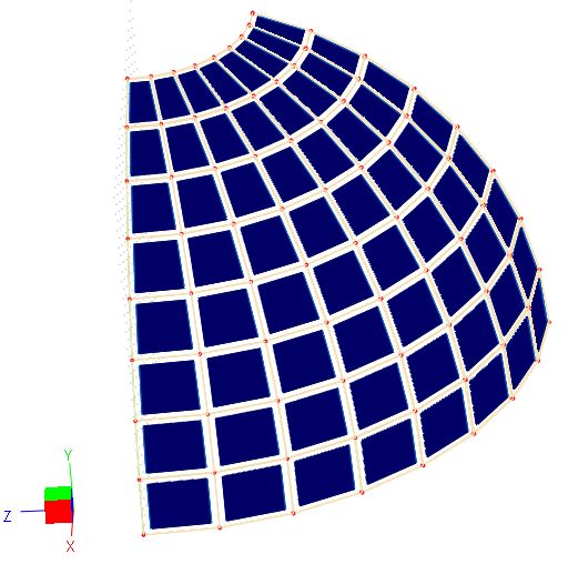
The most efficient way to construct this model in the program is as follows (see the figures below). First generate two sets of side arc members using the command Create > Templates > Arc Members. Then create one shell element at the top using the nodes on the arc members. Delete all generated members. Now use Create > Entities from other Entities > Shells by Nodes to generate 7 more shell elements using the existing nodes on the arcs. Lastly, use Modify > Revolve > Revolve Shells to Bricks command to generate brick elements. This method simplifies the generation procedure.
|
|
|
|
|
|
Reference
[1]. MacNeal & Harder, “A Proposed Standard Set of Problems to Test Finite Element Accuracy”, Finite Elements in Analysis and Design, 1 (1985) 3-20