D-03 (Pinched Cylinder) |
  
|
D-03 (Pinched Cylinder) |
|
Objective
To verify the membrane and bending behavior of the shell element in a curved structure
Problem Description
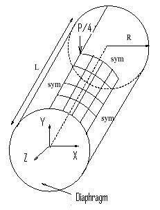
A thin cylindrical shell with diaphragm boundary conditions at both circular ends is loaded with two opposed point loads at the center of the surface.
Material properties: E = 3.0e6 psi, ν = 0.3
Geometric properties: L = 600 in, R = 300 in, t = 3 in
Load: P = 1.0 lb
Finite Element Model
144 shell elements
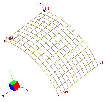
Due to symmetry, one eighth of the cylinder is modeled with a12x12 mesh
Boundary conditions:
Edge N1-N13: Dz, Dox, Doy fixed
Edge N1-N157: Dy, Dox, Doz fixed
Edge N13-N169: Dx, Doy, Doz fixed
Edge N157-N169: Dx, Dy, Doz fixed
Note: N13 is restrained in Dx, Dz, Dox, Doy, Doz.
Model type: 3D Frame and Shell
Results
The deflection under load is given by [Ref 1] as Dy = -1.825e-5 in.
Unit: displacement - in
ENERCALC 3D |
[Ref 1] |
|||
Displacement under load using different shell formulations |
-1.825e-005 |
|||
Compatible membrane |
Incompatible membrane |
|||
Kirchhoff |
MITC4 |
Kirchhoff |
MITC4 |
|
-1.819e-005 |
-1.595e-005 |
-1.833e-005 |
-1.605e-005 |
|
Comments
The results given by ENERCALC 3D are comparable to the referenced values.
It appears that the Kirchhoff thin plate bending formulation yields results close to the referenced values. This is especially true when plate/shell thickness is very thin. Of course, we have to remember that the Kirchhoff plate only applies to rectangular shell elements.
Reference
[1]. Cook, Malkus, Plesha, Witt, “Concept and Applications of Finite Element Analysis” 4th Edition, pp583, John Wiley & Sons, Inc., 2002
