D-02 (Curved Beam) |
  
|
D-02 (Curved Beam) |
|
Objective
To verify the shell element using incompatible membrane and the MITC4 thick plate formulations
Problem Description
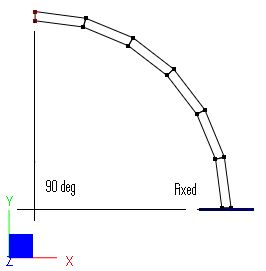
The curved beam shown below [Ref 1] is fixed at the bottom and loaded with two sets of loads at the tip: 1.0 lbf in-plane shear and 1.0 lbf unit out-of-plane shear.
Material properties: E = 1.0e7 psi, ν = 0.25
Plate thickness t = 0.1 in
Curved beam inner radius = 4.12 in, outer radius = 4.32 in, arc = 90o
Finite Element Model
6 shell elements
Model type: 3D Frame & Shell (use incompatible membrane and MITC4 thick plate formulations)
Results
The tip displacements in the direction of loads given by ENERCALC 3D are compared with that given by [Ref 1] as follows:
Unit: displacement - in
Displacement in load direction |
ENERCALC 3D |
[Ref 1] |
In-plane shear (in) |
0.07751 |
0.08734 (see Note) |
Out-of-plane shear (in) |
0.4798 |
0.5022 |
Note: The displacement given by [Ref 1] is smaller than the theoretical calculation based on the following [Ref 2]:
![]() in
in
![]() in4
in4
![]() in
in
Comments
The results given by ENERCALC 3D are very good considering the very coarse mesh employed. We would obtain better results if more elements were used along the beam length.
Reference
[1]. MacNeal & Harder, “A Proposed Standard Set of Problems to Test Finite Element Accuracy”, Finite Elements in Analysis and Design, 1 (1985) 3-20
[2]. Roark & Yong, “Formulas for Stress and Strain” 5th Ed, pp215, McGraw-Hill Inc., 1975
