A-04 (P-delta Beam) |
  
|
A-04 (P-delta Beam) |
|
Objective
To verify the 2nd-order behavior (P-δ) of beam element
Problem Description
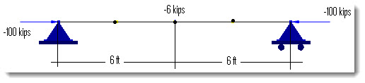
A 12 ft simply supported beam is subjected to a pair of compressive forces of P = -100 kips at the ends and a transverse point force of Q = -6 kips at the middle as shown below [Ref 1].
Material properties: E = 30e6 psi, ν = 0.3
Section: 4 x 4 in (Iz = 21.3333 in4, A = 16 in2)
Finite Element Model
4 beam elements
Model type: 2D Frame (First order and P-Delta)
Results
The displacement and moment at the middle of the beam may be calculated as follows [Ref 1]:
First order:![]() kip-ft;
kip-ft; ![]() in
in
Second order: ![]() rad (= 51.57o)
rad (= 51.57o)![]() kip-ft;
kip-ft; ![]() in
in
Units: displacement – in; moment – kip-in
@ middle of the span |
ENERCALC 3D |
[Ref 1] |
First-order Displacement Dy |
-0.5832 |
-0.583 |
First-order Moment Mz |
18 |
18 |
Second-order Displacement Dy |
-0.8643 |
-0.864 |
Second-order Moment Mz |
25.203 |
25.2 |
Comments
1. The results given by ENERCALC 3D are very close to the referenced values.
2. In order to capture P- δ behavior that is associated with member curvature, the beam must be split into multiple segments. In this example, we used 4 segments and produced satisfactory results. On the other hand, the splitting is not needed to capture P-Δ behavior that is associated with the lateral translation of the frame members.
Reference
[1]. Leet & Bernal, “Reinforced Concrete Design” 3rd Edition, pp294, McGraw-Hill, 1997
