Split |
  
|
Split |
|
Modify > Split provides a few different ways to subdivide the selected members.
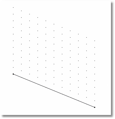
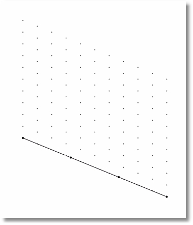
Split > Divide selected members into segments of equal length allows the user to specify the number of segments. When executed, this option will subdivide all selected members into the specified number of members.
leads to
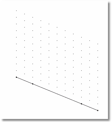
Split > Divide selected members by specifying a distance list allows the user to specify the locations at which the selected members are to be split. The distance list in this command accepts syntax such as:
•12 (to split once at 12 feet)
•12, 24, 10 (to split at 12 feet, then at 24 feet, then at 10 feet)
•3@20 (to split three times, once at 20 feet, once at 40 feet and once at 60 feet)

leads to
Both options of this command offer the option to allow nodes and elements to be merged. When the option is selected to Merge nodes and elements, if the split results in a new node or member that falls exactly on top of another node or member, the program will automatically eliminate the duplicate to avoid problems with model geometry.
Note: After performing a Split command, it is advisable to renumber nodes by clicking Modify > Renumber > Auto Renumber All Nodes prior to running an analysis. This helps to conserve memory usage.
Split > Insert Nodes at Intersections of Selected Members:
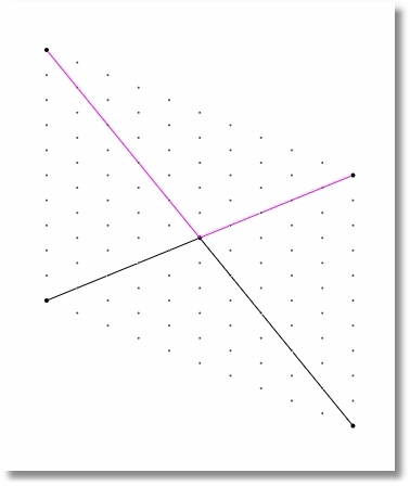
Just because lines cross each other in a plane in ENERCALC 3D does not mean that they are mathematically connected to each other at the intersection point. In fact, unless the members are all connected to a common node at the intersection point, there is no load transfer between the members. This can be thought of as a tension rod running right through a turnbuckle in the opposite diagonal. Each member can each carry load, but there is no connection at that intersection, so they don't share or transfer load at that point.
But now envision a cross brace consisting of HSS sections that connect to a common gusset plate at the intersection. This is a completely different situation that calls for a common node to be placed at the point of intersection.
The Split > Insert Nodes at Intersections of Selected Members command provides an easy way to add that node without having to calculate its coordinates. It acts on selected members, and it simply inserts a new node at all intersection locations of selected members.
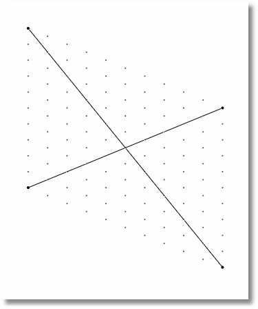
leads to
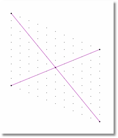
Note: This command ONLY inserts the node(s), but it does not automatically split the selected members so that they frame into that new node. A warning is displayed to this effect with a reminder that if the goal is to connect the members to that new node, the desired command is Split Selected Members at Nodes, which is covered next.
Split > Split Selected Members at Nodes acts on selected members and splits them at any locations where a node lies directly on the member.
It can be particularly useful after using the Split > Insert Nodes at Intersections of Selected Members command, or after placing infill beams that are intended to frame into a supporting girder.
After the command is executed, the member(s) will be split at node locations and all member incidences (connections to nodes) will be maintained and properly displayed in the Members table.
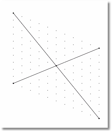
leads to