Steel Member Design Criteria |
  
|
Steel Member Design Criteria |
|
Click Steel Design > Steel Design Criteria > Steel Member Design Criteria to open the Steel Member Design Criteria table. This table controls many aspects of the steel design process.
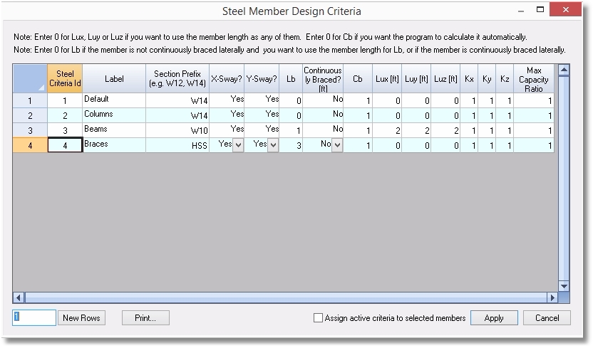
You can create as many Steel Member Design Criteria as you need to satisfy the requirements of your design. Once created, you can assign Steel Member Design Criteria to members graphically.
Label: A freeform text descriptor that has meaning to you.
Section Prefix: Tells the program what family (and optionally what size class) to select from when designing.
X-Sway & Y-Sway: X-sway and Y-sway flags designate if a member is a part of a sway frame in member strong/weak direction, respectively. These flags are only used for checking the validity of Kx and Ky values. For example, if X-sway flag is on and Kx is less than 1.0, the program will give a warning.
Lb & Continuously Braced: These are controls for the unbraced length for bending. If Continuously Braced is set to Yes, then the beam is considered to be continuously braced against flexural buckling, and the value in the Lb column should be specified as zero, because the program is not going to do anything with the value.. If Continuously Braced is set to No, then the program will use the value of Lb as the unbraced length.
Tip: If Continuously Braced is set to No, and the value of Lb is set to zero, then the program will use the full member length as the unbraced length.
Cb: Establishes the value to use for Cb (Lateral-torsional buckling modification factor for nonuniform moment diagrams).
Lux, Luy, Luz, Kx, Ky, and Kz: Length and effective length factors for buckling capacity about all three axes.
Tip: The values with the x subscript refer to buckling about the strong axis of the member (the x axis in AISC nomenclature). The values with the y subscript refer to buckling about the weak axis of the member (the y axis in AISC nomenclature).
Max Capacity Ratio: Establishes the maximum capacity ratio that will be allowed when selecting passing members.
Tip: It is often helpful to use a value of Max Capacity Ratio somewhat less than one when starting to optimize a model, because loads will change when member stiffnesses change and the analysis is rerun. Limiting the Max Capacity Ratio is one way to "pad" the design a little, to allow for some inevitable stress redistribution.
Tip: Use View > Query to check a member's Steel Member Design Criteria.
