Area Loads (on Members) |
  
|
Area Loads (on Members) |
|
Area Load is a way to automatically apply load to members, and it can be convenient for loading many members in an area.
Graphical Method
Click Create > Draw Loads > Area Loads to open the Area Load (on members) dialog.
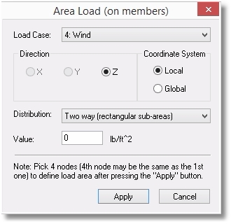
Specify the Load Case with which the new load will be associated. Select the direction of the load and indicate whether the direction selection is to be interpreted as being in the local or global coordinate axis system.
Tip: When the Coordinate System is set to Local, only the Z direction is available.
The Distribution dropdown provides many options. They are best explained graphically (below) by the application of 100 psf load to a rectangular bay with the dimensions shown:
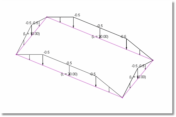
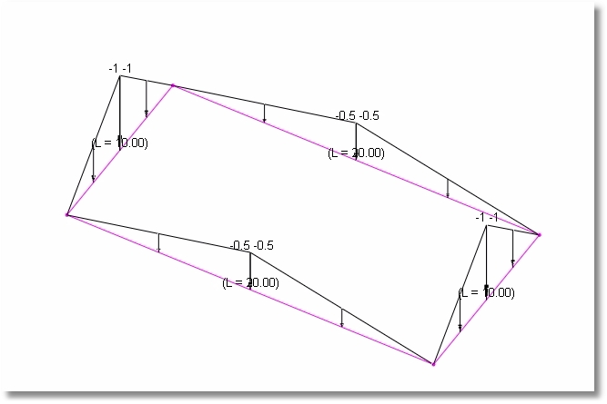
•Two-way (rectangular sub-areas):
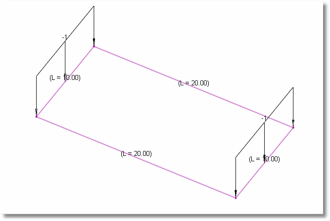
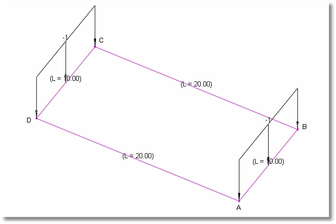
•Short sides (rectangular sub-areas):
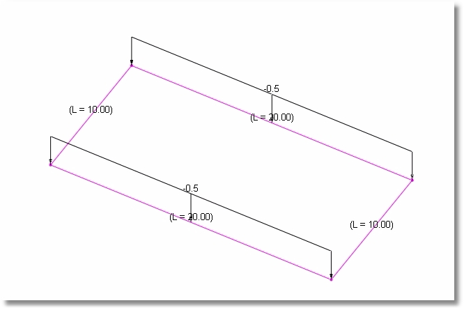
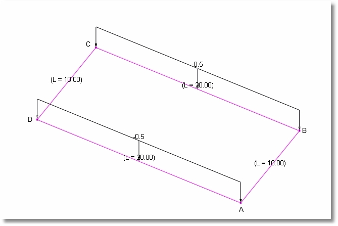
•Long sides (rectangular sub-areas):
•AB and CD sides (rectangular sub-areas):
•BC and AD sides (rectangular sub-areas):
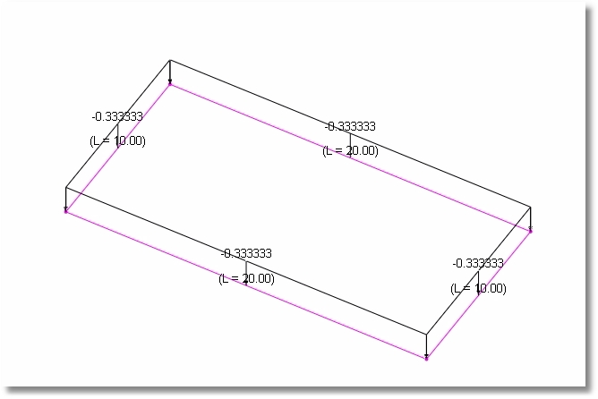
•Centroid-based:
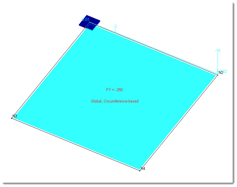
•Circumference-based: (Total load on bay is distributed uniformly along perimeter of bay.)
Enter the value and remember to use the proper algebraic sign for the direction of loading.
After clicking Apply, click on four nodes to define the perimeter of the loaded area. Keep in mind that for some of the load Distribution options, the order of selection of the corners establishes the directionality of the distribution.
Here is what an area load will look like when it is first applied:
Tip: Keep in mind that an Area Load can be dissolved into a series of Line Loads on members by clicking Create > Generate Loads > Convert Area Loads to Line Loads. This may be helpful for visualizing loads like they have been shown in the screen captures above.
Tabular Method
Click Tables > Area Loads to open the Area Loads table.
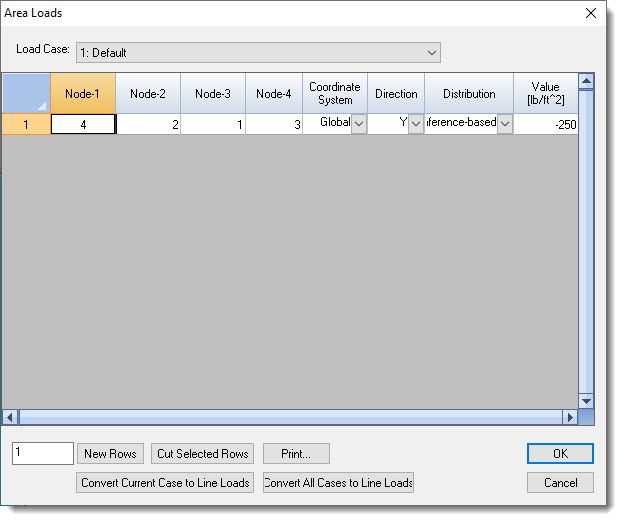
Note that the table has a Load Case dropdown list box at the top.
This table can be useful for reviewing and editing or deleting previously defined Area Loads, but it can also be used to define new area loads by specifying the four perimeter nodes, the Coordinate System and the Direction, the Distribution method and the load intensity Value.
This table also has buttons near the bottom to Convert Current Case to Line Loads and to Convert All Cases to Line Loads. Area Loads don't have to be converted to Line Loads in order to have an effect on the model. But if they are converted to Line Loads, they are no longer visible in the Area Loads table, and will then be displayed in the Line Loads table.
