Line Loads (on Members) |
  
|
Line Loads (on Members) |
|
Line Loads are distributed forces that are applied to members.
Graphical Method
Select the members that are to receive the load. Click Create > Draw Loads > Line Loads. The Line Load dialog opens.
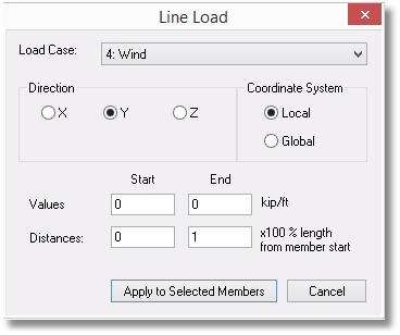
Specify the Load Case with which the new load will be associated.
Select the direction of the load and indicate whether the direction selection is to be interpreted as being in the local or global coordinate axis system.
Specify the magnitude of the force at the start and at the end of the Line Load.
Specify the distances to the start and end of the force (referenced from the starting end of the member) in the form of 0 for the starting end, 0.5 for the midpoint, 1.0 for the ending end, etc.
Tabular Method
Click Tables > Line Loads to open the Line Loads table.
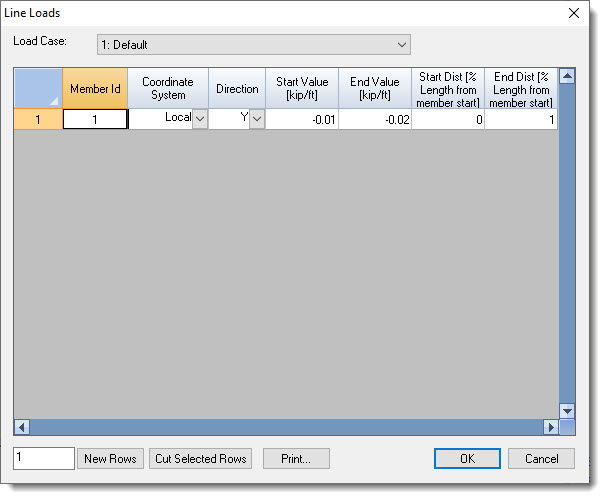
Note that the Load Case dropdown list box is shown at the top of the table. This controls the load case for which loads will be shown.
The table allows existing loads to be reviewed, edited and deleted. It also allows new loads to be defined.
