Torsional Analysis of Rigid Diaphragm with ENERCALC 3D |
  
|
Torsional Analysis of Rigid Diaphragm with ENERCALC 3D |
|
Last revised: Monday, December 22, 2025 at 11:28 AM
The following steps will serve as a guide:
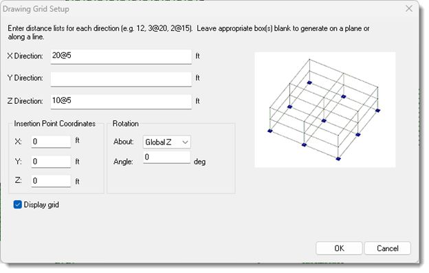
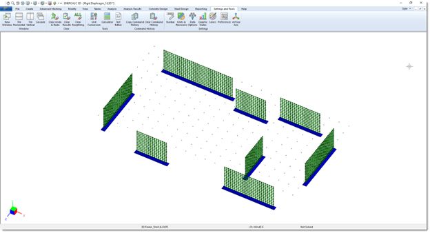
1.Set up a grid in the X and Z axes to match the overall dimensions of the diaphragm.
 |
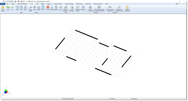
2.Draw one beam to represent the top of each wall in plan:
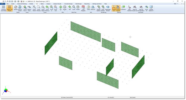
3.Select All, and then Extrude Members to Shells in the -Y direction for the full height of the walls. Select the options to Merge Nodes and Elements and Delete members after extrusion:
 |
4.Mesh the walls using 1 ft x 1 ft approx mesh:
5.Set fixity for the nodes at the bottoms of all walls to Pinned:
6.Model a node at the CG at Y=zero:
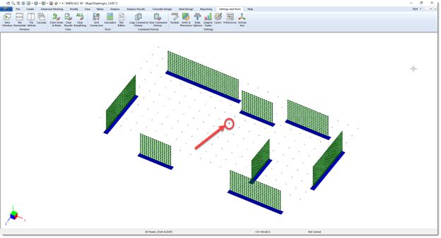
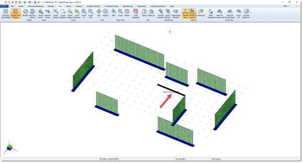
7.Create one rigid link from the node at the CG to any top-of-wall node:
8.Select all nodes at the elevation of the slab:
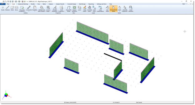
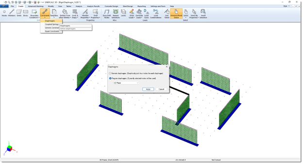
9.Create the rigid diaphragm with Create > Constraints > Diaphragms: Regular, XZ plane:
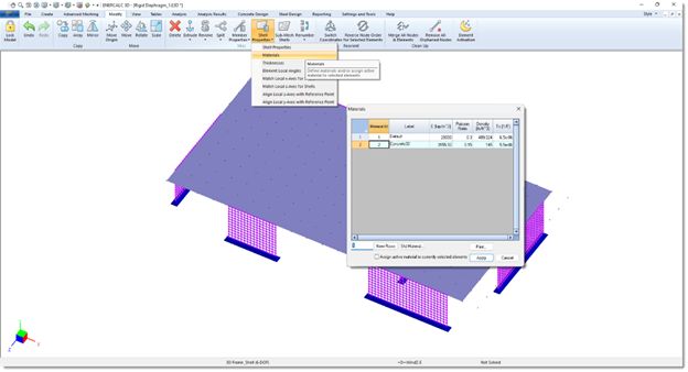
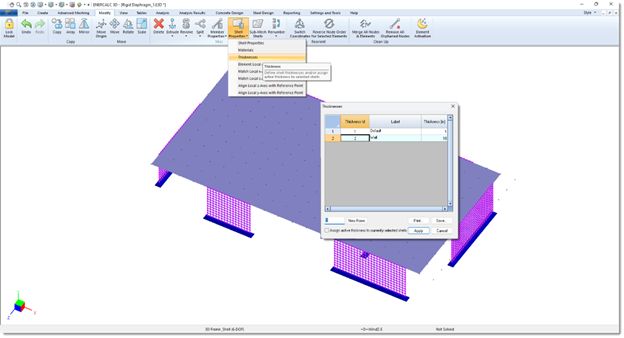
10.Assign material and thickness to all walls:
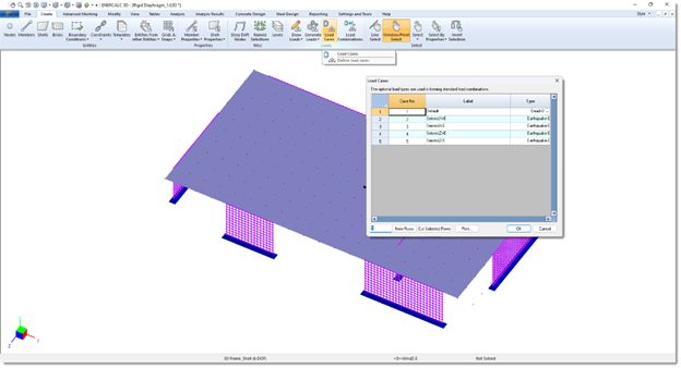
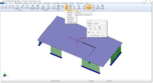
11.Create load cases for all lateral loads that are to be considered:
12.Select only the node at the CG, and apply loads for each load case (including moment):
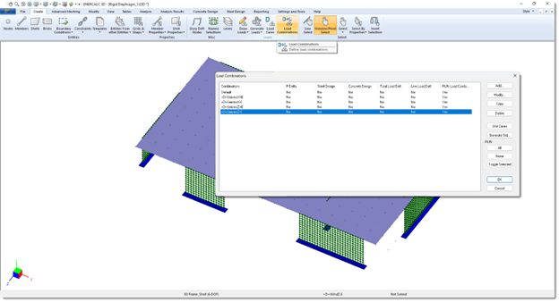
13.Create load combinations:
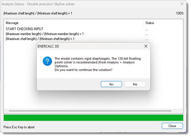
14.Analyze with 64-bit solver. Choose Yes to continue at the message box:
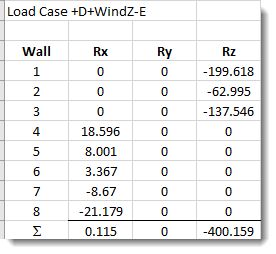
15.Select all nodes at the base of a wall. Show results for selected entities only. View reactions for a particular load combination. The sum at the bottom represents the shears in the selected wall in the named global axis directions:
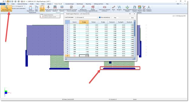
16.As proof of concept, one model with eight walls was run for multiple load combinations. The load combination of +D+WindZ-E was studied. Below are the reactions at the bases of all eight walls in all three directions. The sums show that the reactions equate sufficiently close to the applied loads to prove that the method works: