Generic Elements Show Zero Forces in One of the Global Directions |
  
|
Generic Elements Show Zero Forces in One of the Global Directions |
|
Last revised: Monday, December 22, 2025 at 11:28 AM
I’m seeing zero force results in one of the global directions for my Generic Resisting Elements even though I have elements oriented in both directions. What’s causing this?
This situation typically occurs when the Generic Resisting Elements' global participation has been defined by both altering their orientation and neglecting stiffness in alternating directions. The result is that the global system ends up with no net stiffness along a particular global direction.
Before looking at an example, it’s important to note the following:
•The element orientation controls how the element’s local axes align with the global coordinate system.
•If flexibility is neglected along a given local axis, the element has no stiffness and therefore provides no resistance in that corresponding local direction.
Example:
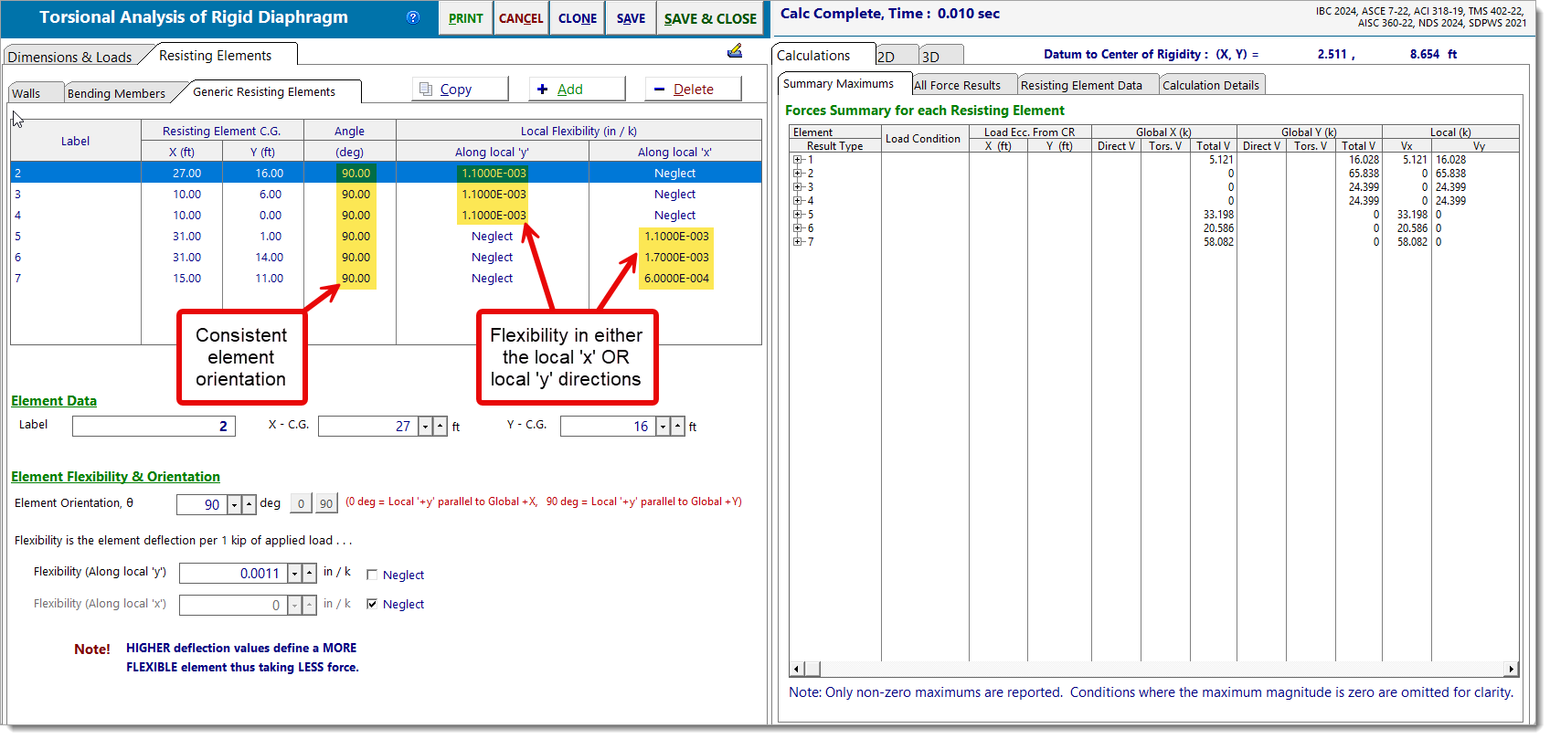
In this case, all elements have been oriented at either 0° (local 'y' parallel to global 'X') or 90° (local 'y' parallel to global 'Y'). Additionally, element flexibility has been neglected in either the local 'y' direction or the local 'x' direction.
Notice the following:
•Elements oriented at 0° (local 'y' parallel to global 'X') have also neglected flexibility in the local 'y' direction. The result is no stiffness in the global 'X' direction.
•Elements oriented at 90° (local 'y' parallel to global 'Y') have also neglected flexibility in the local 'x' direction. Again, the result is no stiffness in the global 'X' direction.
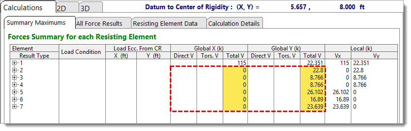
The net effect is that, even though the elements appear to be arranged to resist in both the global 'X' and 'Y' directions, their stiffness configuration actually limits participation to the global 'Y' direction only.
How to Fix It
If you want the elements to resist forces in specific global directions, it’s best to control their participation using only one of the following methods:
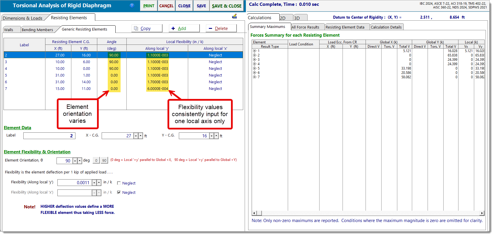
Method 1: Vary element orientation, Relevant local flexibility axis remains constant
Input flexibility values consistently for one local axis only (commonly local 'y', which aligns well with 2D diagrams), and then adjust the element orientation to align it with the desired global direction.
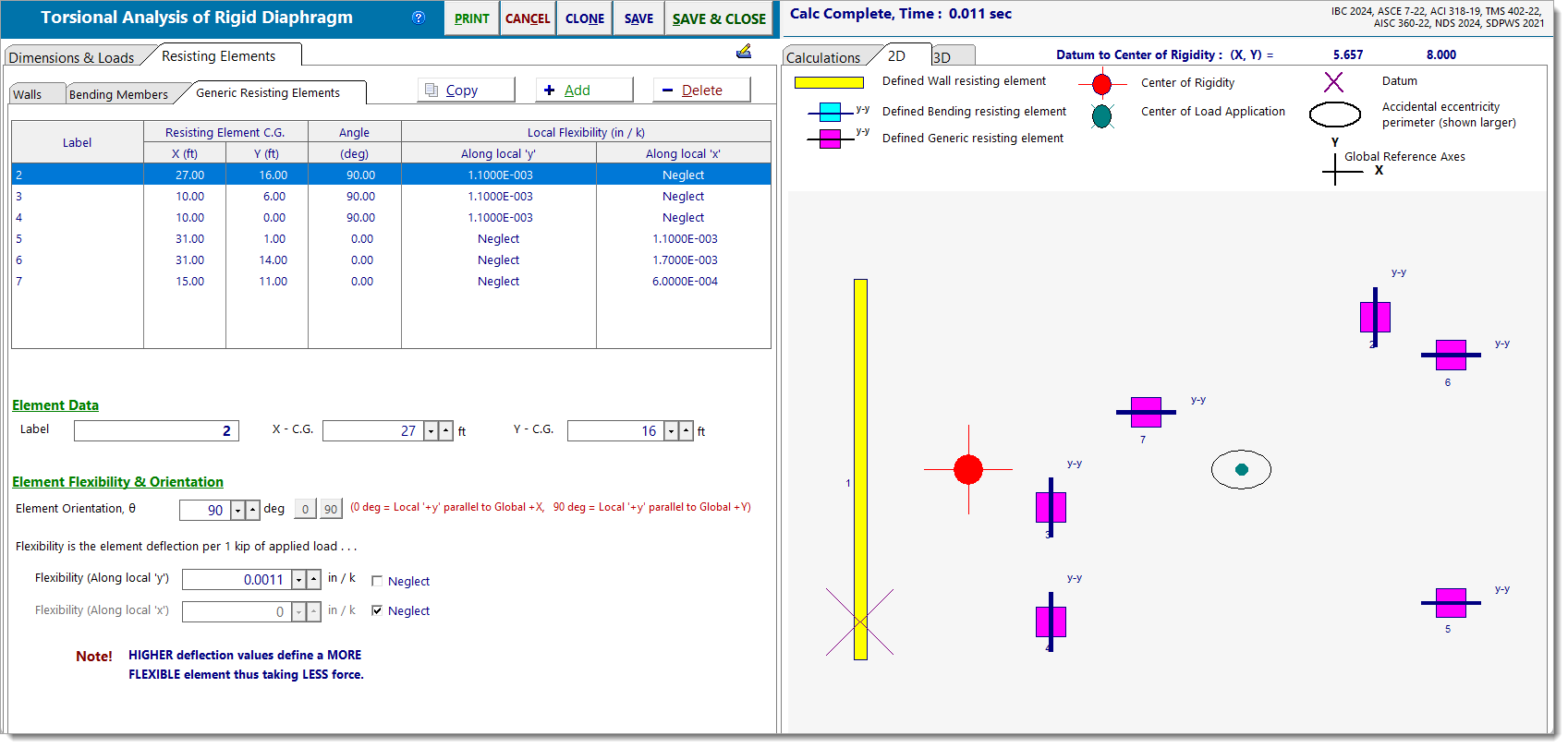
Method 2: Vary the relevant local flexibility axis, Element orientation remains constant
Set the element orientation to 90° so that the local axes align with the global coordinate system, and then define flexibility in either the local 'x' or local 'y' directions.