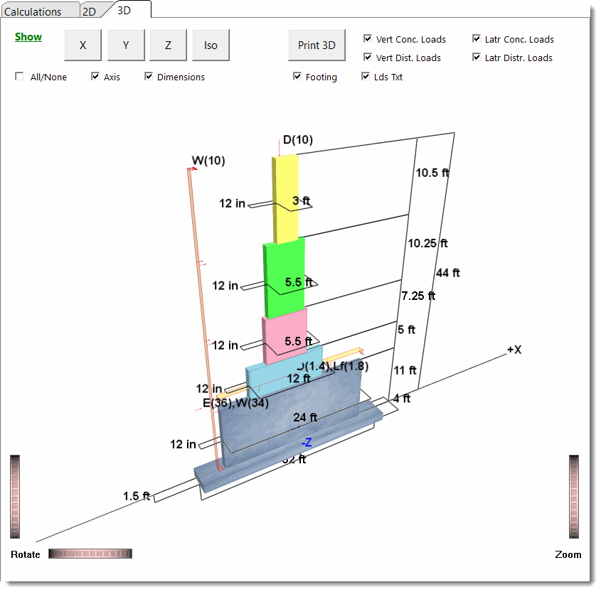
This module allows the design of concrete shear walls including multi-story walls with no openings but with up to five levels of differing length, height and thickness.
General
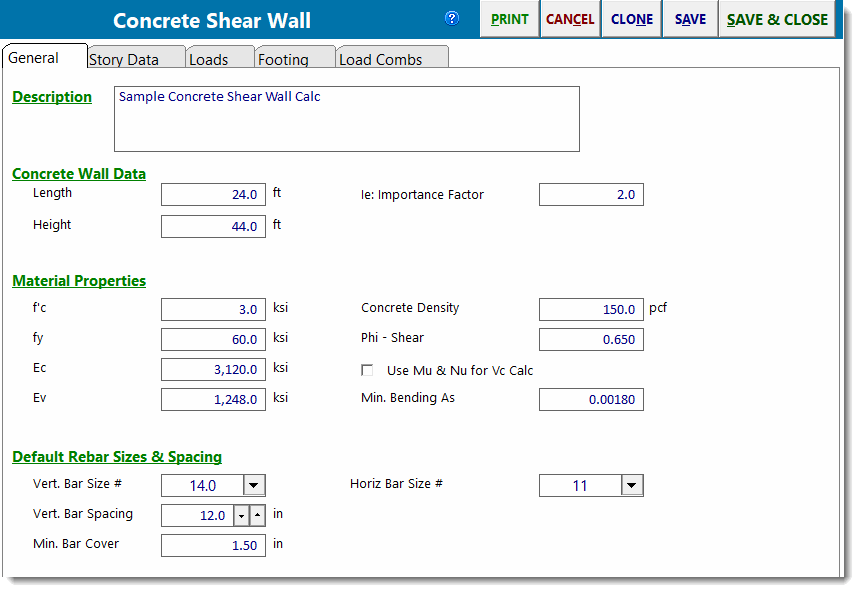
Length specifies the total length of the lowest level of the wall.
Height specifies the total height of the wall. On the next tab you can divide that total height into up to five different wall portions.
f'c is the concrete strength.
fy is the yield stress of rebar.
Ec is the bending modulus of elasticity.
Ev is the shear modulus of elasticity.
SDS and R are used to calculate the in-plane portion of the wall weight to be applied as a seismic load.
Default Rebar Sizes & Spacing: specify size, spacing, and cover for horizontal and vertical rebar. These inputs are used for drawing the graphics to scale, as well as for determining limiting reinforcing percentages.
Story Data
This tab is where you specify the distinct wall levels for the wall.
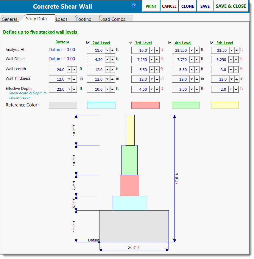
Analysis Height locates the bottom edge of the wall section and is where the maximum shear and bending stress will be calculated. This is the user-defined height at which the analysis of a particular wall section will be performed. All moments, shears, and vertical loads at this height will be calculated using all applied lateral and vertical loads and the wall self weight above this point. The other wall data items specified in the same column will be used between this analysis height and the next higher level indicated in the column to the right.
ALWAYS DEFINE ANALYSIS HEIGHTS IN INCREASING ORDER FROM LEFT TO RIGHT. This is needed due to the manner in which the module calculates the heights by comparing heights of adjacent sections.
Wall Offset is the distance that this wall section is offset from the left-most edge of the bottom-most wall section. Please refer to the diagram to further understand this item. Because this module can be used with a walls that have their length changes with height, you must enter the offset from the bottom wall section to the LEFT EDGE of the wall section. This enables the module to calculate the actual X-Distance to the center of gravity of the wall.
Wall Length is the length of the wall section. Maximum length is the overall wall length - offset. Enter the length to be used in the analysis of the particular wall section. Please note that if the Wall length + Offset is greater than the Wall Length + Offset for the level below, this indicates that the section OVERHANGS the section below it. This is not allowed.
Wall thickness is the thickness of this wall section. Enter the thickness to be used in the analysis of a particular wall section. This thickness will be used only between the Analysis Height for that section up to the analysis of the next higher section (or Total Wall Height if it is the highest section).
Effective Depth locates the tension rebar in the panel, and is used to calculate "shear depth" for calculation of actual shear stresses. As with beams, the Effective Depth in a shear wall is measured from the compression edge of the wall to the centroid of the tension chord rebar.
Loads
This main tab has four sub-tabs that allow you to enter four types of loads.
Vertical loads can be of dead, live, roof live and snow types.
Lateral loads can be of seismic and wind types.
Add wall weight to dead loads will tell the module to calculate the weight of the wall above each analysis height and include it in the vertical dead loads to calculate applied axial stress. It also is used for footing design when that option is selected.
Add wall weight as SEISMIC load will calculate the wall self weight, apply the lateral weight seismic factor and "E" load combination factor. The resulting load will be applied at the wall center to calculate shear and overturning due to that portion of the wall. This is used for values at the analysis height, for the effect of that level's seismic weight on the levels below, and for footing overturning and sliding calculations.
Vertical Point Loads
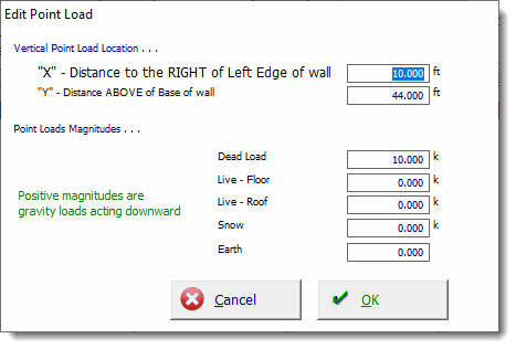
Use this tab to apply point loads to the wall. You can specify an "X" and "Y" distance from the lower-left corner of the lower wall so that the load can be located anywhere on the defined walls.
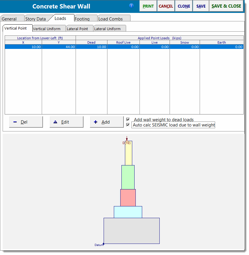
Use the [Add] and [Edit] buttons to change the values of applied loads. Clicking either button displays this window:
Vertical Uniform Loads
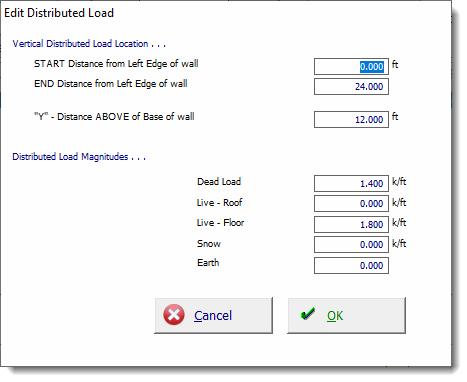
Use this tab to apply uniform loads to the wall. You can specify a "Y" distance from the bottom of the lower wall so that the load can be located at any height.
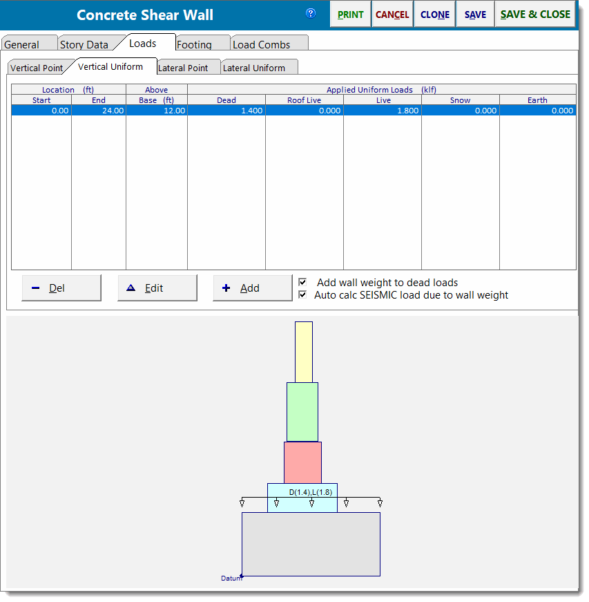
Use the [Add] and [Edit] buttons to change the values of applied loads. Clicking either button displays this window:
Lateral Point Loads
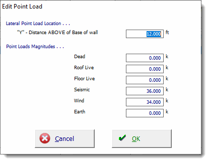
Use this tab to apply point lateral loads to the wall. You can specify a "Y" distance from the bottom of the lower wall so that the load can be located at any height.
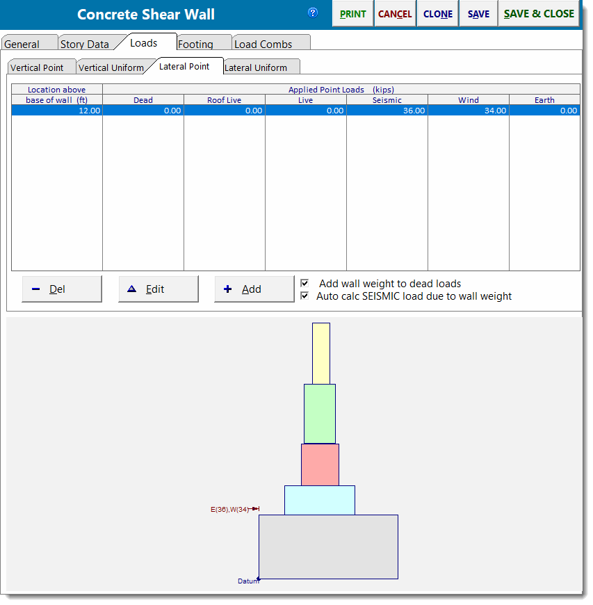
Use the [Add] and [Edit] buttons to change the values of applied loads. Clicking either button displays this window:
Lateral Uniform Loads
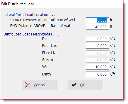
| Use this tab to apply uniform lateral loads to the wall. You can specify a Start and End location to define the extent of the lateral load. |
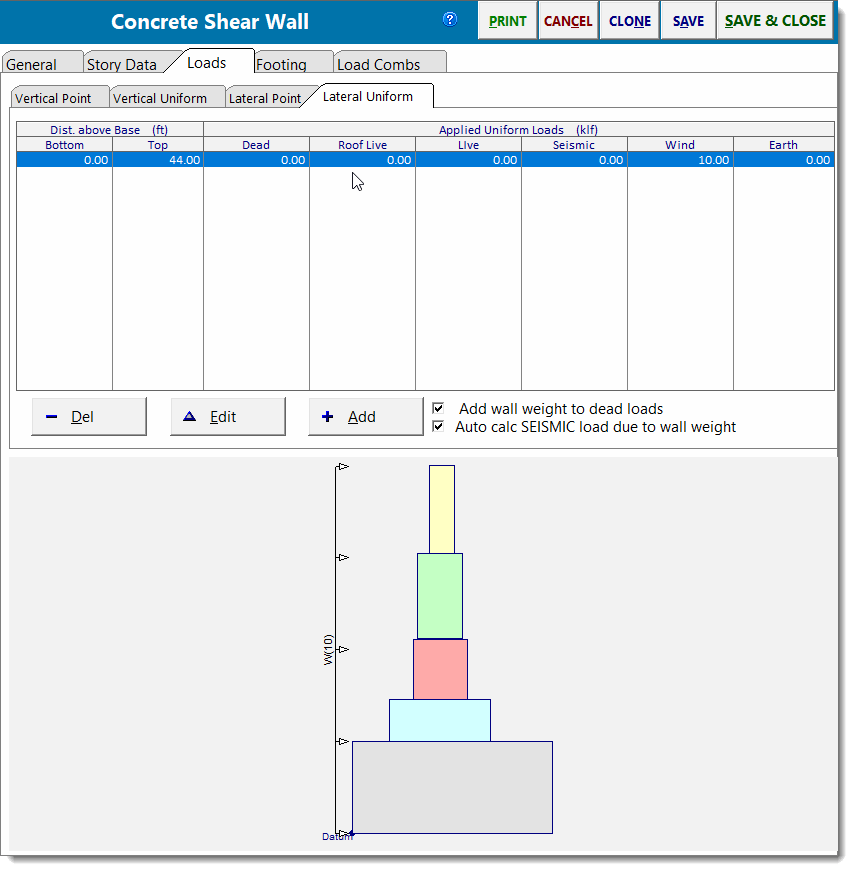
Use the [Add] and [Edit] buttons to change the values of applied loads. Clicking either button displays this window:
Footing
You also have the option to specify a footing under a shear wall by selecting the Specify a Footing ![]() checkbox. The dimensions of the footing are specified using Distance @ Left and Distance @ Right.
checkbox. The dimensions of the footing are specified using Distance @ Left and Distance @ Right.
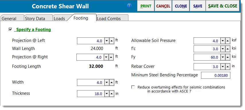
Distance @ Left is the distance that the footing projects past the left edge of the wall (meaning the lower wall level for a multi-story type wall).
Distance @ Right is the distance that the footing projects past the right edge of the wall (meaning the lower wall level for a multi-story type wall).
Rebar is assumed to exist only at the bottom of the footing to resist tensile forces from the vertical loads and increased pressure due to overturning forces. Tension in the top of the footing in cases where no upward soil pressure exists and the footing weight creates a downward net force IS IGNORED.
Load Combinations
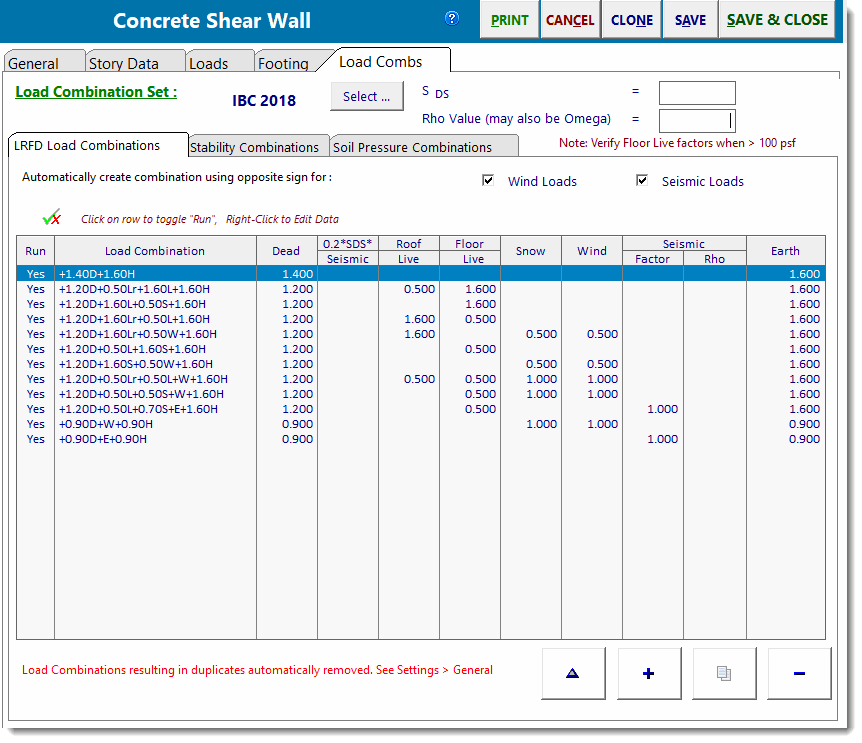
The typical load combination tab for strength design of concrete is provided.
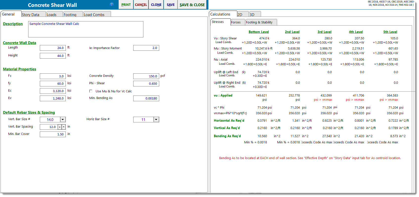
Stresses
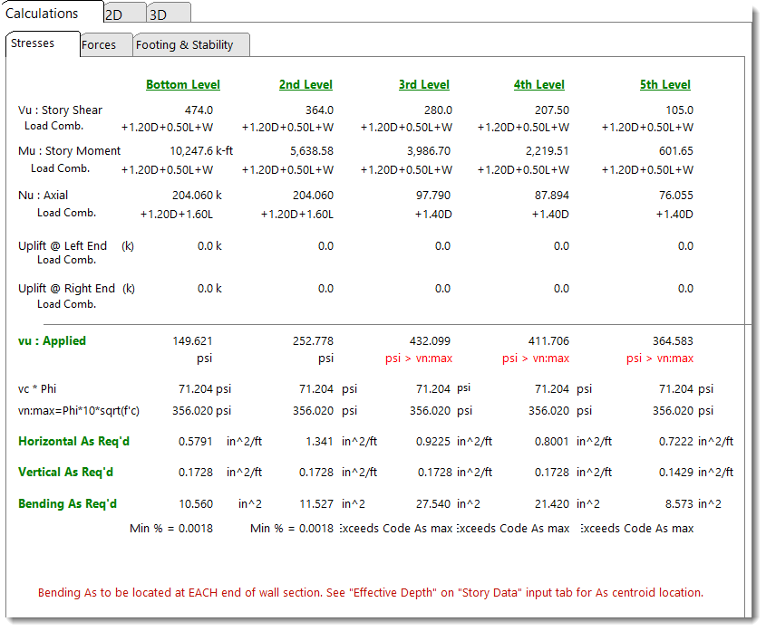
Provides a summary of each level.
In the top portion you will see the calculated shear, moment and axial loads at the analysis height you have specified. These values are due to wall self weight and applied vertical and lateral loads from that analysis height and above.
In the bottom portion of the screen, the unit shear stresses, shear steel required and end reinforcing for bending tension in that wall section are reported. All calculations are per ACI.
Forces
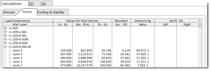
This tab provides the detailed force values for each wall level and for each load combination.
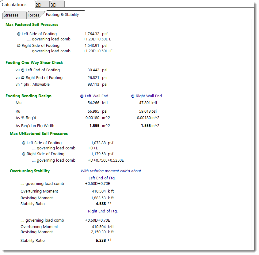
Footing & Stability
This tab provides the calculated service and factored load soil pressure, one-way shear and bending at the end of the wall.
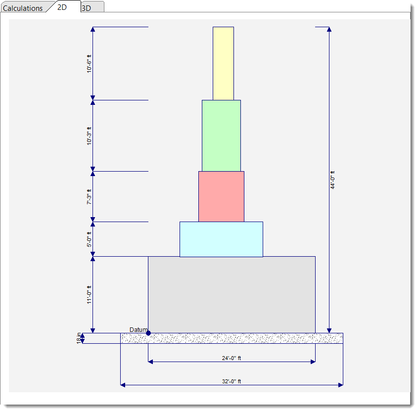
2D Sketch
3D Rendering
