D-05 (Hemispherical Shell with Point Loads) |
  
|
D-05 (Hemispherical Shell with Point Loads) |
|
Objective
To verify the membrane and bending behavior of the MITC4 shell element in a doubly-curved, very thin shell structure
Problem Description
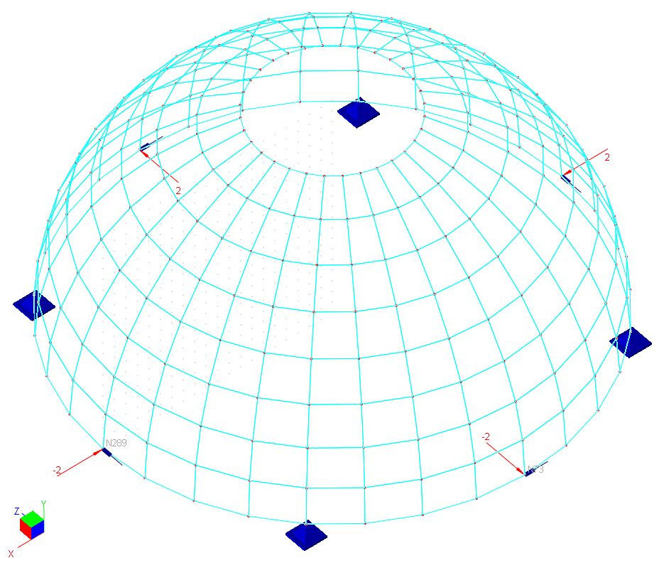
The hemispherical shell below [Ref 1] has a radius of 10 ft and a thickness of 0.04 ft. The equator is a free edge and is loaded with four 2-kip point loads alternating in sign at 90 degrees intervals. The edge of the hole at the top (72 degrees from the axis of revolution) is free.
Material: E = 6.825e7 kip/ft^2; v = 0.3;
Thickness: t = 0.04 ft;
Radius R = 10 ft.
Finite Element Model
8 x 32, 16 x 64 and 32 x 128 shell elements
For simplicity of boundary conditions, symmetry of the structure is not considered. The boundary restraints are applied to prevent instability of the structure.
Model type: 3D Frame and Shell
Results
The results given by ENERCALC 3D compare well with benchmark values.
Units: displacement – ft
Radial displacement at load point
|
8 x 32 mesh |
16 x 64 mesh |
32 x 128 mesh |
MITC4 Compatible |
9.272e-2 |
9.289e-2 |
9.334e-2 |
MITC4 Incompatible |
9.292e-2 |
9.313e-2 |
9.346e-2 |
Benchmark Value |
9.400e-2 |
9.400e-2 |
9.400e-2 |
Comments
The results given by ENERCALC 3D are comparable to the benchmark values.
This problem is one of the more challenging benchmark tests for shell elements. The reason is that the shell is doubly curved and shell thickness is very small in comparison with its span (radius). Both membrane and bending strains contribute significantly to the radial displacement at the load point. This example shows the superiority of the MITC4 shell element.
We could have taken advantage of the symmetry and only model one quadrant of the structure. The boundary condition requires a little more thinking but is still straightforward in this case. An example is included with the program to illustrate this approach.
Modeling Tips
The most efficient way to construct this model in the program is as follows. First generate arc members using the command Create > Templates > Arc Members. Then use Modify > Revolve > Revolve Members to Shells command to generate doubly curved shell elements.
Reference
[1]. MacNeal & Harder, “A Proposed Standard Set of Problems to Test Finite Element Accuracy”, Finite Elements in Analysis and Design, 1 (1985) 3-20
