C-03 (Bathe Membrane Nodal Resultants) |
  
|
C-03 (Bathe Membrane Nodal Resultants) |
|
Objective
To verify the calculation of nodal resultants for compatible membrane formulation
Problem Description
The cantilever plate shown below is modeled with 2 x 2 mesh using compatible membrane formulation.
Material properties: E = 2.7e6 psi, ν = 0.3
Thickness t = 0.1 in
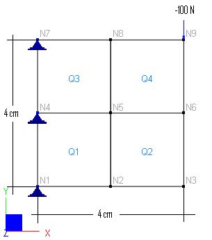
Finite Element Model
4 shell elements
Model type: 2D Plane Stress (using compatible formulation)
Results
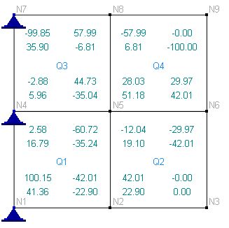
The nodal resultants given by ENERCALC 3D are identical to those given by [Ref 1].
As shown below, the nodal resultants are displayed in two lines at each node of each element. The first line denotes the local x component and the second line does the local y component.
The unit is N.
Comments
The results given by ENERCALC 3D are identical to the referenced values.
The nodal resultants represent forces that hold each element in equilibrium. Finite element solutions must always satisfy nodal point equilibrium and element equilibrium. This is true whether a coarse or fine mesh is employed.
Reference
[1]. Bathe, “Finite Element Procedures”, pp 179, Prentice-Hall, Inc., 1996
