B-01 (Plate Patch Test) |
  
|
B-01 (Plate Patch Test) |
|
Objective
To verify the plate (MITC4 thick plate formulation) passes the patch test
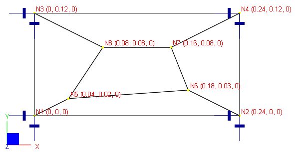
Problem Description
A plate of size 0.12 x 0.24 in is subjected to forced displacements at the four corners as shown below. The boundary conditions are:
w = 1.0e-3(x2 + xy + y2) / 2
![]()
![]()
Material properties: E = 1.0e6 psi, ν = 0.25
Geometry: nodal coordinates are shown in the parenthesis below, thickness t = 0.001 in
Finite Element Model
5 shell elements
Model type: 2D Plate Bending (MITC4 thick plate formulation)
Forced displacements on boundary nodes:
Units: displacement – in; rotation - rad
Boundary Nodes |
Displacement Dz |
Rotation Dox |
Rotation Doy |
1 |
0 |
0 |
0 |
2 |
2.88e-5 |
1.20e-4 |
-2.40e-4 |
3 |
7.20e-6 |
1.20e-4 |
-6.00e-5 |
4 |
5.04e-5 |
2.40e-4 |
-3.00e-4 |
Results
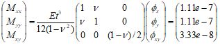
The displacements of internal nodes can be calculated based on the boundary conditions. The generalized strains and stresses may be calculated as follows:
![]() ;
;
![]() ;
;
![]() ;
;
The constant stresses are also given by [Ref 1].
Units: displacement – in; rotation - rad
Nodes |
ENERCALC 3D |
Theoretical |
||||
Dz |
Dox |
Doy |
Dz |
Dox |
Doy |
|
5 |
1.40e-6 |
4.00e-5 |
-5.00e-5 |
1.40e-6 |
4.00e-5 |
-5.00e-5 |
6 |
1.935e-5 |
1.20e-4 |
-1.95e-4 |
1.935e-5 |
1.20e-4 |
-1.95e-4 |
7 |
2.24e-5 |
1.60e-4 |
-2.00e-4 |
2.24e-5 |
1.60e-4 |
-2.00e-4 |
8 |
9.60e-6 |
1.20e-4 |
-1.20e-4 |
9.60e-6 |
1.20e-4 |
-1.20e-4 |
Units: moment – lb-in/in
ENERCALC 3D |
[Ref 1] |
||||
Mxx |
Myy |
Mxy |
Mxx |
Myy |
Mxy |
1.11e-7 |
1.11e-7 |
3.33e-8 |
1.11e-7 |
1.11e-7 |
3.33e-8 |
Comments
The results given by ENERCALC 3D are identical to the theoretical and referenced values.
A patch test consists of creating a small “patch” of elements and then imposing an assumed displacement field at the boundary nodes. The assumed displacement field is chosen such that it causes a constant stress in the mesh. To pass the patch test, computed displacements at the interior nodes must be consistent with the assumed displacement field and the computed stresses must be constant. Patch tests are important because they ensure solution convergence—so that increasing mesh fineness results in more accurate results.
The MITC4 plate formulation passes the patch test. The Kirchhoff plate formulation passes the patch test if the elements are rectangular. The Kirchhoff plate formulation is not applicable here.
Reference
[1]. MacNeal & Harder, “A Proposed Standard Set of Problems to Test Finite Element Accuracy”, Finite Elements in Analysis and Design, 1 (1985) 3-20
[2]. Cook, Malkus, Plesha, Witt, “Concept and Applications of Finite Element Analysis” 4th Edition, pp238, John Wiley & Sons, Inc., 2002
