A-02 (Simple 3d-Beam) |
  
|
A-02 (Simple 3d-Beam) |
|
Objective
To verify the behavior of the 3d beam element
Problem Description
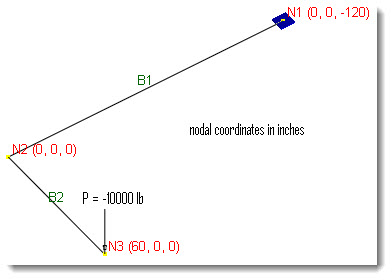
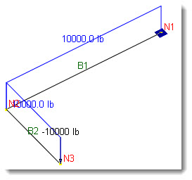
A simple 3d beam of round section is fixed at one end and loaded at the tip of the other end as shown below.
Lengths: L1 = 120 in, L2 = 60 in
Material properties: E = 2.9e7 psi, G = 11.15e6, ν = 0.3
Section properties: Ix = Iy = 1017.88 in4, J = 2023.75 in4, Az = 10 in2
Tip Force P = 1e4 lb
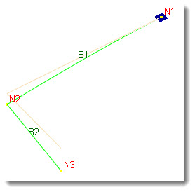
Finite Element Model
2 beam elements
Model type: 3D Frame & Shell (shear deformation ignored)
Results
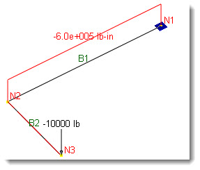
The tip vertical displacement Dy at N3 may be calculated as [Ref 1]:
Unit: displacement - in
|
ENERCALC 3D |
Theoretical |
Displacement Dy @ N3 |
-0.4098 |
-0.4098 |
Comments
The results given by ENERCALC 3D are identical to the theoretical values.
The moment, shear and deflection diagrams are shown below for illustration purposes.
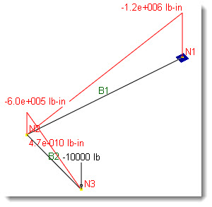
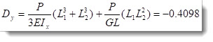
Major Moment Diagram (Mz)
Torsion Diagram (Mx)
Shear Diagram (Vy)
Deflection Diagram
Reference
[1]. Long & Bao, “Structural Mechanics”, pp146, People’s Educational Publishing House, China, 1983.
