Starting and Ending Nodes |
  
|
Starting and Ending Nodes |
|
As we saw when we learned how to add a member, members are always defined by two nodes: a starting node and an ending node. The beam can be thought of as spanning from the starting node to the ending node.
The diagram below shows that beam 541 has nodes numbered 217 and 218:
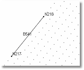
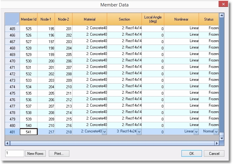
The data in the table below indicate that beam 541 starts at node 217 and ends at node 218.
This establishes a directionality that can be very useful when modeling and when interpreting results. It also forms the basis for the Member Local Axis system covered in the next section.
Note: The direction and orientation of a member can be revised by some commands that we will cover in the section on Editing Model Geometry.
