Member Local Axes |
  
|
Member Local Axes |
|
All members have a default local axis system. It is useful for a variety of things like defining member end releases, defining member end offsets, applying loads, defining member local angle, and interpreting results.
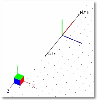
The default member local axis system is defined as follows:
1.The member local x (red) axis is defined as a vector pointing from the starting node to the ending node.
2.The default member local z (blue) axis is defined by the vector cross product of local x cross global Y. Think of this by pointing your right fingers in the direction of the local x axis, and then curl your fingers to envision swinging that local x axis into the global Y axis. The direction of your right thumb indicates the direction of the vector cross product, and therefore indicates the direction of the local z axis.
Note: The one condition where this rule cannot be applied is with vertical members, because it is not possible to calculate the vector cross product of two parallel vectors. So in that case, ENERCALC 3D adopts the convention that the local z axis will be oriented parallel to the global Z axis.
3.The default member local y (green) axis is defined by the rule that says in a Cartesian coordinate system, z cross x equals y. Think of this by pointing your right fingers in the direction of the local z axis, and then curl your fingers to envision swinging that local z axis into the local x axis. The direction of your right thumb indicates the direction of the vector cross product, and therefore indicates the direction of the local y axis.
A subsequent topic in the Editing Model Geometry section will discuss ways that the member local axis system can be revised to something other than this default orientation.
