Shell Local Axes |
  
|
Shell Local Axes |
|
As was the case with members, shells also have a local axis system that is important when applying loads and interpreting results.
Envision a quad shell where Node 1 = A, Node 2 = B, Node 3 = C and Node 4 = D.
The default shell local axis system is displayed at the geometric center of a shell, and the axis orientation is defined as follows:
1.The default shell local z (blue) axis is perpendicular to the shell. It is defined by the cross product of vectors AB and AC. Think of this by pointing your right fingers in the direction of AB, and then curl your fingers to envision swinging AB into AC. The direction of your right thumb indicates the direction of the vector cross product, and therefore indicates the direction of the local z axis.
2.The shell local x (red) axis is defined as follows:
•For horizontal shells that are parallel to global XZ plane, local x is parallel to global X.
•For non-horizontal shells, local x is perpendicular to a plane formed by global Y and local z.
3.The default member local y (green) axis is defined by the rule that says in a Cartesian coordinate system, z cross x equals y. Think of this by pointing your right fingers in the direction of the local z axis, and then curl your fingers to envision swinging that local z axis into the local x axis. The direction of your right thumb indicates the direction of the vector cross product, and therefore indicates the direction of the local y axis.
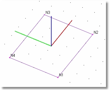
Note: local x and local y always fall in the plane of the shell, and local z is always perpendicular to the plane of the shell. The positive local z axis occurs on the "top" side of the shell.
