Grids |
  
|
Grids |
|
Grids are a graphical aid for model construction.
They are completely optional, and can be turned on and off by View > Toggle Grid Display, or by toggling the F7 key.
Grids can be useful for a few purposes:
•Provide a sense of orientation in the beginning, when very few members have been placed.
•Helpful for establishing a sense of scale in the early stages of modeling.
•Most important use is geometric control in the form of creating snap points to known coordinates when constructing model geometry.
Defining Grids:
1. Click View > Drawing Grid Setup.
2. Specify the desired spacings of dots in one, two or all three global axis input fields.
•Specifying spacings in only one axis input box will create a line of dots along that axis.
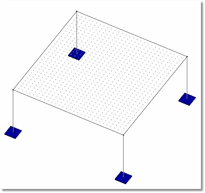
•Specifying spacings in two axes input boxes will generate a two-dimensional array of dots that lies in the plane of the two axes specified, and is probably the most commonly used.
•Specifying spacings in three axes input boxes will generate a three-dimensional array of dots, which can sometimes be difficult to interpret if the dot spacing is too close.
•Spacings can automatically be generated with syntax like 20@0.5.
•Spacings can also be manually specified with comma delimited lists such as 30, 30, 28, 30, 30.
3. Specify the insertion point coordinates to move the defined grid around in the global coordinate system if necessary.
4. Specify a rotation angle and axis of rotation if necessary.
•Can be useful for defining members or shells that lie in a sloping plane, such as a roof.
