Wood Column |
  
|
Wood Column |
|
This module designs wood columns that are subject to axial loads and lateral bending loads about both axes.
The user can select ASD or LRFD design methods and has access to a large built-in database of wood sizes and NDS species stress grades. Values of KF and phi are automatically determined and applied for the LRFD method.
All calculations are according to the NDS code.
The screen capture below shows the full screen for wood column design. See items below for descriptions of items that are specific to the Wood Column module.
For general description of the module, end fixity, loads, and load combinations click here. For slenderness description click here.
General
The Design Stresses area bubbled in the screen capture below is unique to the wood column selection. This area enables you to specify the base design values for the wood species and grade of interest.
You can either enter these values manually, or you can click the ![]() button to display the Wood Stress Database.
button to display the Wood Stress Database.
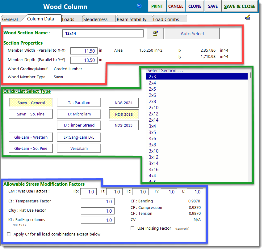
Column Data
All of the information on this tab is unique to a wood column.
The area bubbled in red is where you specify the column cross section. Use the ![]() button to display the built-in database of wood sections (solid-sawn, glulam, and engineered wood products are available). You can also enter the values manually.
button to display the built-in database of wood sections (solid-sawn, glulam, and engineered wood products are available). You can also enter the values manually.
The area bubbled in blue provides allowable stress modification factors that you can specify. Please note that CF or CV values are automatically filled in. CF values are determined from the size and stress grade of the member (No. 1 and Utility grades have different values). CV values are calculated when a glu-lam section is specified. Note that this section allows for the specification of the Repetitive Member factor. If the Repetitive Member factor option is selected, the program then offers the option to specify a value for the Wall Stud Repetitive Member Factor as defined by the NDS Special Design Provisions for Wind and Seismic (SDPWS). If the option is selected to specify a Wall Stud Repetitive Member Factor, it will only be applied to load combinations that include wind. Be sure to review the appropriate section of SDPWS for requirements on the use of this factor, as well as the values to be used for various sizes of dimension lumber.
The area in green provides quick access to the built-in wood section database. Simply click the button of the section type and the list on the right will be populated automatically from the appropriate database. Then just click on a section to have its data loaded into the entries in the red area.
Note: The flat use factor will only be applied if it is specified by the user. In addition, it is important to understand how the factor will be applied in situations where built-up columns are designed. The flat use factor is supposed to be applied when bending occurs about the weak axis of the individual laminations. But the program does not actually understand the orientation of individual laminations in a built-up column as of July 2018. So for consistency, the program is set up to look at the overall dimensions of a built-up column cross section, and then to apply the flat use factor only when considering bending about the overall weak axis. This requires the designer's consideration, because the weak axis of the overall built-up section may or may not correspond to the weak axis of the individual laminations.
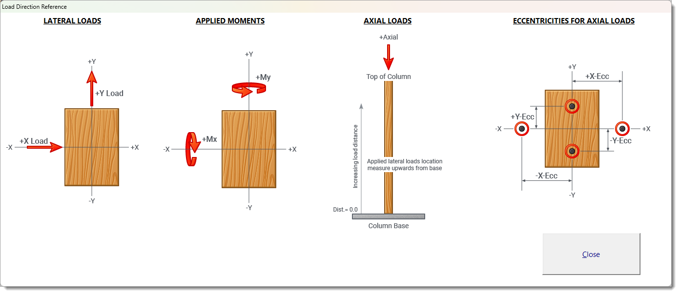
Loads
Load Reference Guide: Clicking this button opens a pop-up window that displays the positive sign conventions used in the module.
For more information on the Loads tab, please refer to the Columns topic.
Results
This tab provides a summary of the stress ratios, reactions and deflections for the column.
Max Axial + Bending Stress Ratio is the governing load combination for the column. Listed is the governing load load combination, the NDS formulas that is used and the location of the maximum stress ratio above the base of the column. Please note maximum stress ratio is what is being reported because it governs the design.....not necessarily the highest axial or bending stress.
Max Shear Stress Ratio will probably never govern for a column design but is presented here with the governing load combination, location and allowable/actual stress values.
Lateral Load Reactions and Deflections are the result of applied lateral loads.
Design Maximum Combinations
This tab lists the resulting maximum stress ratios for each load combination. This list is created by examining the detailed list (on the next tab) and determining the governing stress ratios for each load combination.
Detailed Results - Shears
This tab lists the detailed shear results at small increments along the height of the column for each load combination.
Note! This list scrolls to the right to display more information.
Detailed Results - Axial
This tab lists the detailed axial results at small increments along the height of the column for each load combination.
Detailed Results - X-X Moments
This tab lists the detailed X axis moment results at small increments along the height of the column for each load combination.
Detailed Results - Y-Y Moments
This tab lists the detailed Y axis moment results at small increments along the height of the column for each load combination.
Detailed Results - Service Load Deflections
This tab reports the deflections at incremental locations along the height of the column, for each service load condition (i.e. for individual load cases and for a set of built-in service load combinations), along each axis.
Reactions - Per Load Combination
This tab displays the support reactions calculated for each load combination defined in the Load Combs > Reaction Combinations tab.
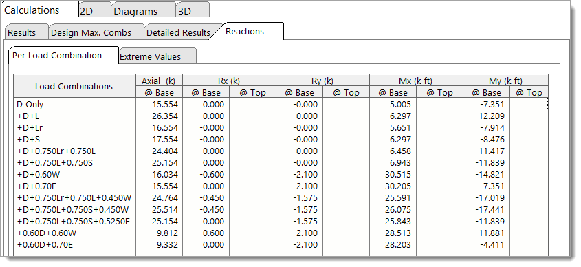
Reactions are reported at both the base and top of the column (where applicable), and include the following:
Axial @ Base (k): Axial reaction at the base of the column.
•Positive values indicate compression (downward force).
•Negative values indicate tension (uplift).
Rx @ Base/Top (k): Horizontal reaction in the X-direction at the base and top.
•Positive values act in the global +X direction (to the right when looking down at the top of the column).
•Negative values act in the global -X direction (to the left when looking down at the top of the column).
Ry @ Base/Top (k): Horizontal reaction in the Y-direction at the base and top.
•Positive values act in the global +Y direction (upward on screen when looking down at the top of the column).
•Negative values act in the global -Y direction (downward on screen when looking down at the top of the column).
Mx @ Base/Top (k-ft): Moment reaction about the X-axis at the base and top.
•Positive values follow the right-hand rule. Point your right thumb in the direction of the +X-axis (to the right when looking down at the top of the column), and your curled fingers indicate the direction of the moment.
•Negative values follow the right-hand rule. Point your right thumb in the direction of the -X-axis (to the left when looking down at the top of the column), and your curled fingers indicate the direction of the moment.
My @ Base/Top (k-ft): Moment reaction about the Y-axis at the base and top.
•Positive values follow the right-hand rule. Point your right thumb in the direction of the +Y-axis (upward on screen when looking down at the top of the column), and your curled fingers indicate the direction of the moment.
•Negative values follow the right-hand rule. Point your right thumb in the direction of the -Y-axis (downward on screen when looking down at the top of the column), and your curled fingers indicate the direction of the moment.
Reactions - Extreme Values
This tab summarizes the maximum and minimum reaction forces and moments that occur at the top and bottom of the column across all defined load combinations.
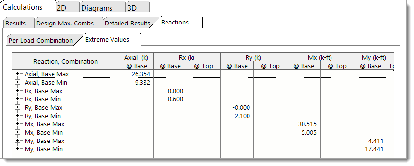
The following values are reported (where applicable):
•Axial, Base Max and Axial, Base Min: The max and min vertical axial reactions at the base of the column.
•Rx, Base Max and Rx, Base Min: The max and min horizontal reactions in the X-direction at the base and top.
•Ry, Base Max and Ry, Base Min: The max and min horizontal reactions in the Y-direction at the base and top.
•Mx, Base Max and Mx, Base Min: The max and min moment reaction about the X-axis at the base and top.
•My, Base Max and My, Base Min: The max and min moment reaction about the Y-axis at the base and top.
Notes:
•"Max" values represent the "most positive" results (i.e., closest to positive infinity), while "Min" values represent the "most negative" results (i.e., closest to negative infinity).
•Reaction components with no results are omitted from the table. For example, a cantilever column will not display any Top extreme values, since no reactions exist there.
•Zero values are shown as blank in the table for clarity.
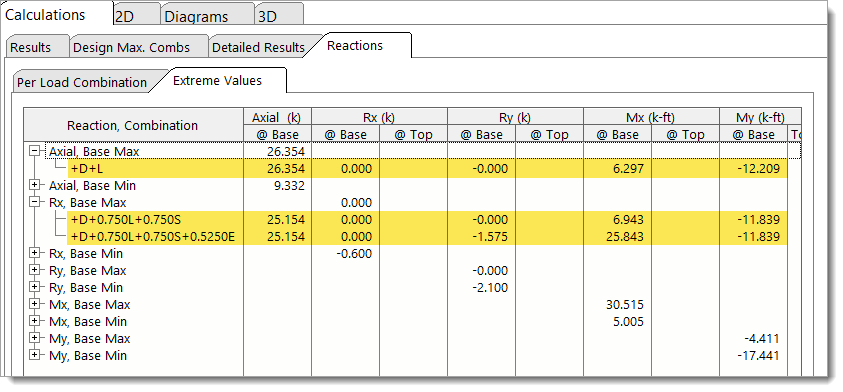
The results are presented in a tree-structured table. Each row shows an extreme value and can be expanded to reveal:
•The load combination(s) that produced that extreme value.
•The associated reaction components for those combinations.
•If multiple load combinations result in the same extreme value, all contributing combinations will be listed.
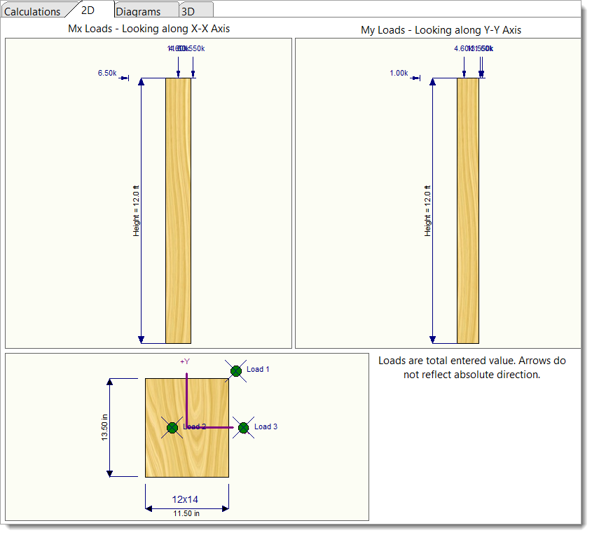
2D Sketch
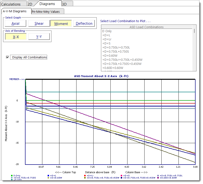
Diagrams - A-V-M-D Diagrams
This tab provides comprehensive charting capability to view graphs of axial load, shear, moment, and deflection along the length of the member. Note that the graphs are oriented such that the right end of the graph represents the column base, and the left end of the graph represents the column top. This was done to maximize the scale of the graph based on the screen area available.
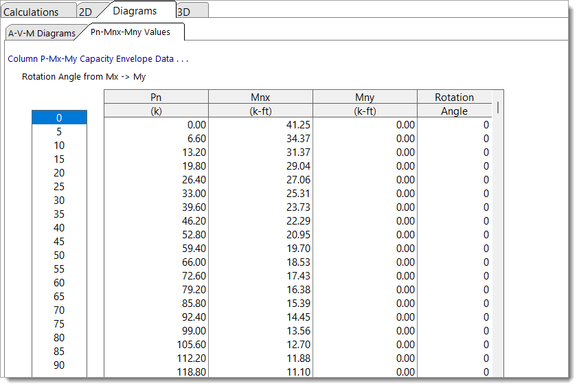
Diagrams - Pn-Pnx-Mny Values
This tab allows you to see the moment capacities about each axis given a certain allowable axial load.
This is mostly for reference and can be considered a reverse application of the load capacity calculations.
3D Rendering
 <
<