Steel Member Bracing Definition |
  
|
Steel Member Bracing Definition |
|
Last revised: Thursday, January 29, 2026 at 02:59 PM
Steel member bracing can be defined for each member by following these steps:
1. Define the Steel Member Design Criteria by navigating to the Steel Design tab > Steel Design Criteria > Steel Member Design Criteria.
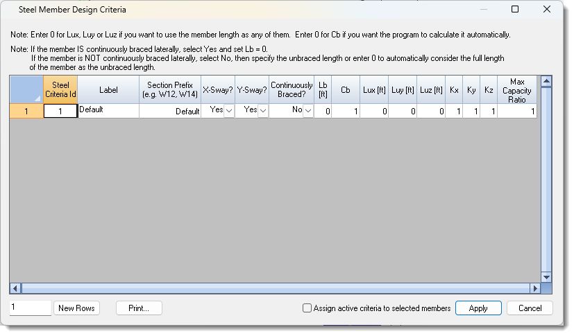
2. For column-type flexural buckling, enter 0 for Lux, Luy, or Luz if you want to use the full member length. Otherwise, specify the unbraced length. Ensure you define the effective length factors Kx, Ky, and Kz as well.
3. For beam-type lateral-torsional buckling, if the member is continuously laterally braced, select "Yes" for "Continuously Braced?" and set Lb = 0. If the member is not continuously laterally braced, select "No" and specify the unbraced length, or enter 0 to automatically consider the full length of the member.
4. Continue this process to define as many steel member design rules as necessary for your project. Note that the Steel Member Design Criteria can be applied to multiple members, so it may not be necessary to define a new rule for each member.
5. Take note of the Steel Criteria ID for each rule, as you will need to associate these rules with the corresponding elements in the next step. Click OK when finished.
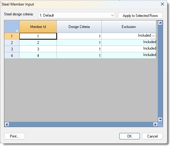
6. Go to the Steel Design tab > Steel Member Input and input the Steel Criteria ID's from the previous step within the Design Criteria column. Repeat this for each member as required.
 <
<