Summary Section of Stem Tab |
  
|
Summary Section of Stem Tab |
|
Last revised: Thursday, January 29, 2026 at 02:41 PM
The summary section indicates the results of the Stem design at-a-glance.
| Interaction Ratio: | The interaction ratio indicates the efficiency of your design, not to exceed 1.0. |
| For masonry using ASD this is the computed ratio of fa/Fa + fb/Fb. |
| For concrete and masonry using LRFD it is Mactual/Mallowable. |
| The weight of the stem will be included only if there is added axial load. For masonry stems, Fa is calculated by considering the wall as unsupported with "K" = 2.0. Since even a very small axial load will activate the unsupported height/slenderness calculation for masonry stems, we suggest you do not enter an axial load unless it is significant (e.g. greater than, say, 3000 plf.). |
| Actual Moment: | This is the maximum moment due to the lateral pressures and applied loads above the "Design Height" location entered. Note that when concrete is used, all soil pressures and loads are factored per default Load Factors for evaluation of moments and shears. |
| Allowable Moment: | This is the allowable moment capacity. It is Allowable Stress Design (ASD) for masonry, or based upon Strength Design for concrete and when LRFD is specified for masonry. For concrete strength design, the maximum reinforcing steel percentage is controlled by equilibrium at the prescribed strain limits. |
| Total Force: | This is the total lateral force from loads applied above the "Check Design at Height" location entered. This force is factored for concrete and masonry using the LRFD method. Forces applied to compute overturning, sliding, and soil pressure are not factored. |
| Actual Shear: | For masonry stems, the shear stress is calculated as Total Shear Force / An. For concrete stems, the shear stress is calculated as Total Shear Force / (12" * 'd'). |
| Allowable Shear: | For masonry stems designed by ASD, the allowable shear stress is calculated per TMS 402-16 Eqn. 8-26 as follows: |
where need not exceed 1.0
Since no contribution of shear strength is assumed from reinforcing steel in a retaining wall, nor is the stem a partially grouted shear wall, TMS 402-16 Eqn. 8-22 reduces to Fv = Fvm
An upper bound limit Fv,max is imposed on Fv such that Fv ≤ Fv,max where:
a) where
b) where
c)and Fv,max is linearly interpolated for values of between 0.25 and 1.0.
For masonry stems designed by LRFD, the nominal shear strength is calculated per TMS 402-16 Eqn. 9-20 as follows:
where need not exceed 1.0
Since no contribution of shear strength is assumed from reinforcing steel in a retaining wall, nor is the stem a partially grouted shear wall, TMS 402-16 Eqn. 9-17 reduces to vn = vnm
An upper bound limit vn,max is imposed on vn such that vn ≤ vn,max where:
a) where
b) where
c)and vn,max is linearly interpolated for values of between 0.25 and 1.0.
For concrete stems designed per ACI 318-14 and earlier, or ACI 318-25 and later with Use simplified Vc equation (Section 13.3.6.1.1) enabled, the nominal shear strength is calculated as follows:
φ vn = φ * 2 * λ * √(f'c), where φ = 0.75.
For concrete stems designed per ACI 318-19, or ACI 318-25 and later with Use simplified Vc equation (Section 13.3.6.1.1) disabled, the nominal shear strength follows the one-way shear provisions of §22.5 and Table 22.5.5.1 (referenced by §13.3.6.1 and §7.5.3.1):
φ vn = φ * 8 * λs * λ * (ρw)1/3 * √(f'c), where φ = 0.75.
Note: The one-way shear capacity assumes no transverse reinforcement in the stem. Therefore, Av < Av,min, and equations (a) and (b) from Table 22.5.5.1 are not applicable.
This value is also subject to additional limits per §22.5.5.1.1:
Lower bound: φ * λ * √(f'c) (ACI 318-25 and later only)
Upper bound: φ * 5 * λ * √(f'c)
Rebar Lap & Embedment Lengths:
Regardless of the stem material, there are two fundamental lengths to calculate: lap splice length and development length. These values are summarized in the "Rebar Lap & Embedment Lengths" table which can be accessed from the button on the Stem Design Values tab.
The following presents the formulas used and the limits applied to generate the values in that table:
Straight Development Length of Rebar in Concrete: (Applies to all referenced codes)
ld calc = (3/40) * (fy / sqrt(f'c)) * (psis / 2.5) * (bar size / 8)
psis = 0.8 for bar sizes #6 and smaller, 1.0 for bar sizes #7 and larger
ld report = ld calc but not less than 12 inches
(This is Eq. (25.4.2.3a) from ACI 318-14 and Eq. (25.4.2.4a) from ACI 318-19 with appropriate assumptions for bar location, clear cover, spacing, transverse reinforcing, and epoxy coating.)
Lap Splice Length of Rebar in Concrete: (Applies to all referenced codes)
ls = 1.3 * ld calc but not less than 12 inches
Hooked Embedment of Rebar in Concrete:
For ACI 318-14:
but not taken less than 8 * db or 6" per Section 25.4.3.1
Where:
fy = Rebar yield stress for the bottom stem segment.
ψe = Epoxy factor per Table 25.4.3.2 (taken as 1.0).
ψc = Cover factor per Table 25.4.3.2 (user-specified as 0.7 or 1.0).
ψr = Confining Reinforcement factor per Table 25.4.3.2 (user-specified as 0.8 or 1.0).
λ = Lightweight factor per Table 25.4.3.2 (taken as 1.0).
f'c = Concrete compressive strength of the footing.
db = Rebar diameter for the bottom stem segment.
Users may optionally choose to reduce the calculated ℓdh by the ratio of required-to-provided rebar area (As,required / As,provided) by clicking the associated check box on the Stem tab.
For ACI 318-19:
but not taken less than 8 * db or 6" per Section 25.4.3.1
Where:
fy = Rebar yield stress for the bottom stem segment.
ψe = Epoxy factor per Table 25.4.3.2 (taken as 1.0).
ψr = Confining Reinforcement factor per Table 25.4.3.2 (user-specified as 1.0 or 1.6).
ψo = Location factor per Table 25.4.3.2 (user-specified as 1.0 or 1.25).
ψc = Concrete Strength factor per Table 25.4.3.2 (calculated as the minimum of f'c/15,000 + 0.6 and 1.0).
λ = Lightweight factor per Table 25.4.3.2 (taken as 1.0).
f'c = Concrete compressive strength of the footing.
db = Rebar diameter for the bottom stem segment.
For ACI 318-25:
but not taken less than 8 * db or 6" per Section 25.4.3.1
Where:
fy = Rebar yield stress for the bottom stem segment.
ψe = Epoxy factor per Table 25.4.3.2 (taken as 1.0).
ψs = Size factor per Table 25.4.3.2 (taken as 1.0 for #9 bars and smaller, 1.15 for #10 and #11 bars, 1.3 for #14 bars, and 1.5 for #18 bars).
ψcc = Cover factor per Table 25.4.3.2 (user-specified as 0.7 or 1.0).
ψr = Confining Reinforcement factor per Table 25.4.3.2 (user-specified as 0.8 or 1.0).
λ = Lightweight factor per Table 25.4.3.2 (taken as 1.0).
f'c = Concrete compressive strength of the footing.
db = Rebar diameter for the bottom stem segment.
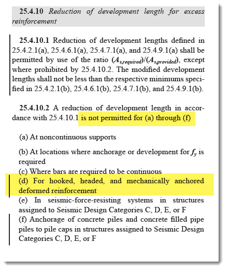
Note: Section 25.4.10 for ACI 318-19 and later editions does not permit reducing hooked development length by the ratio of (As,required / As,provided):
Development Length of Rebar in Masonry designed by ASD: (Applies to all referenced codes)
ld calc = (0.002) * (bar size / 8) * fs
fs = actual stress in rebar
ld report = ld calc but not less than 12 inches
(This is the IBC equation.)
Lap Splice Length of Rebar in Masonry designed by ASD: (Applies to all referenced codes)
ls = Factor * ld calc but not less than 12 inches or 40 bar diameters
Factor = 1.5 in regions where design tensile stresses in reinforcement are greater than 0.8 * fs, otherwise 1.0.
(As of build 20.22.10.9, the program conservatively assumes a value of 1.5 for the "Factor" referenced above.)
Development Length of Rebar in Masonry designed by LRFD: (Applies to all referenced codes)
ld calc = (0.13) * (bar size / 8)^2 * fy * gamma / (K * sqrt(f'm))
gamma = 1.0 for #3 through #5 bars, 1.3 for #6 through #7 bars, and 1.5 for #8 through #9 bars
K = 1.5 for #3 through #5 bars, 2.0 for #6 through #9 bars
ld report = ld calc but not less than 12 inches
(This is the ACI equation by direct reference from IBC. The value of K has conservatively been set to the required clear cover for the selected bar exposed to earth.)
Lap Splice Length of Rebar in Masonry designed by LRFD: (Applies to all referenced codes)
ls = 1.0 * ld calc but not less than 12 inches and need not be GREATER than 72 bar diameters
General Notes on Rebar Lap & Embedment Lengths:
For concrete stems, a Class B lap splice is assumed, therefore the lap length is the bar development length x 1.3. Concrete is assumed to be normal weight, and bars are assumed to be plain (not epoxy coated).
Concrete development lengths are computed per ACI 318.
For the bottom Design Height only (Ht. = 0.00), this displays the required hooked bar embedment into the footing. It assumes a bar with a 90° bend and at least a 12-diameter extension.
The minimum footing thickness required is based upon this embedment depth plus the clearance you have specified below the bar (usually 3 inches). If this totals more than the footing thickness you have chosen, a warning message will be displayed.
Note that if the bar extends straight down into a key, it must be embedded by a depth equal to the development length.
The program does not reduce embedment length by stress level unless the user selects the checkbox labeled Reduce Hook Embedment by Percent Rebar Stress.
The program never reduces lap splice lengths by the stress ratio. It is not permitted by the referenced codes.
 <
<