Point Load on Slab |
  
|
Point Load on Slab |
|
Last revised: Wednesday, February 18, 2026 at 12:03 PM
Design Approach and Sources
This module calculates the load-carrying capacity of an unreinforced concrete slab-on-grade subjected to isolated concentrated loads, such as storage rack legs not supported by a building structure. This application is outside the scope of ACI 318.
The design approach implemented in this module is based on the simplified analytical method presented by Azzi & Laird (2008), derived from the nonlinear finite-element research of Shentu, Jiang, and Hsu (1997).
This method is based on an elasto-plastic representation of slab behavior and is intended to estimate the ultimate load-carrying capacity of a slab-on-grade subjected to a concentrated load. Unlike traditional linear-elastic approaches, this formulation accounts for cracking and post-cracking behavior of the concrete slab.
For further information see:
(1) Shentu, Jiang, and Hsu (1997). Load-Carrying Capacity for Concrete Slabs on Grade. Journal of Structural Engineering, ASCE.
(2) Azzi and Laird (2008). Load-Carrying Capacity of Concrete Slabs-on-Grade Subject to Concentrated Loads. STRUCTURE Magazine.
(3) Jlilati, Brown, and Tang (2019). Comparative Investigation of Two Design Methods for Slab-on-Grade Foundations Subjected to Concentrated Loads. ISEC Press.
(4) Federal Emergency Management Agency (FEMA). (2005). Seismic Considerations for Steel Storage Racks Located in Areas Accessible to the Public (FEMA 460). Prepared by the Building Seismic Safety Council.
Slab Capacity Equations
The nominal load-carrying capacity is calculated using the following equation:
Pn = β * 1.72 [(ks * R1 / Ec) 10,000 + 3.60] * Fr * d2 [Equation 1, Azzi and Laird (2008)]
Where
ks: Modulus of subgrade reaction of the soil, pci
R1: sqrt(Plate Width * Plate Length) / 2, inches
Ec: Concrete elastic modulus, psi
Fr: Tensile strength of the concrete = ft' * sqrt(f'c), psi
d: Slab thickness, inches
β: Load reduction factor for thick slabs; Azzi & Laird (2008) use β = 1.0 for slab thicknesses less than 7 inches and β = 0.85 for slab thicknesses of 7 inches or greater
ft': Factor used to calculate the tensile strength in flexure of concrete; a value of 7.5 is commonly used for normalweight concrete, though alternative values may be selected based on engineering judgment and supporting research
ASD and LRFD Implementation
When ASD is selected, the nominal load-carrying capacity (Pn) is reduced using a user-defined Factor of Safety (FS) and compared directly to the applied load (Pu):
FS = Pn / Pu
When LRFD is selected, the nominal load-carrying capacity (Pn) is reduced using a user-defined strength reduction factor (Φ). The Factor of Safety remains available as an additional user-defined input. In this case, it is generally expected that Φ will account for the primary resistance reduction and that the Factor of Safety may therefore be set to 1.0; however, users may specify alternative values consistent with their design approach and engineering judgment.
FS = Φ * Pn / Pu
This module provides flexibility in how resistance reductions are applied. Users should ensure that the combined effect of Φ and FS reflects their intended design assumptions and should avoid unintentionally double-counting safety margins.
Factor of Safety Considerations
This module allows the user to specify a Factor of Safety (FS) to reduce the nominal load-carrying capacity for design use. Earlier applications of this method commonly used a Factor of Safety of 3. Experimental studies evaluating this approach indicate that a Factor of Safety of 6 may be more appropriate for design applications. Users should select a Factor of Safety consistent with their intended performance objectives and applicable engineering judgment.
These Factor of Safety values are most directly applicable when the method is used in an ASD framework. When LRFD is selected, users should ensure that the combined effect of the selected strength reduction factor (Φ) and any additional Factor of Safety reflects their intended performance objectives.
Minimum Adjacent Load
The nominal load-carrying capacity (Pn) equation assumes that the load acting on the slab is unique and no other nearby loads are affecting the calculation.
To assist in the evaluation of slabs-on-grade, this module also provides a calculation of the distance that the closest load may be without affecting the calculated slab capacity. The calculation given below is based on research by Packard, Pickett and Ray, and Spears and Panarese, and is also discussed in ACI 360R-92.
In this module the distance is calculated as 1.5 * "Radius of Relative Stiffness" given by the following equation:
b = [ Ec * d3 / (12 * (1-u2) * ks)] 0.25 [Equation 3, Azzi and Laird (2008)]
Where
b: Radius of relative stiffness, inches
Ec: Concrete elastic modulus, psi
d: Slab thickness, inches
u: Poisson's ratio
ks: Modulus of subgrade reaction of the soil, pci
General
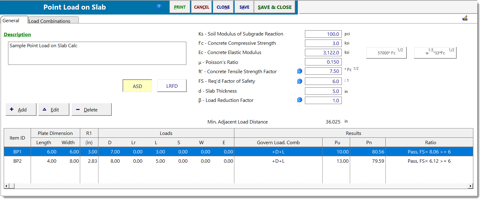
This module is designed to allow the user to create a table of loads applied to a particular concrete slab and supporting soil with one set of material properties.
You can then use the [Add], [Edit] and [Delete] buttons to add a set of applied loads and base plate dimensions. From this data all load combinations are used to determine the maximum axial force. For the plate dimension you specify, the maximum load capacity for the point load application is calculated and compared with your required factor of safety.
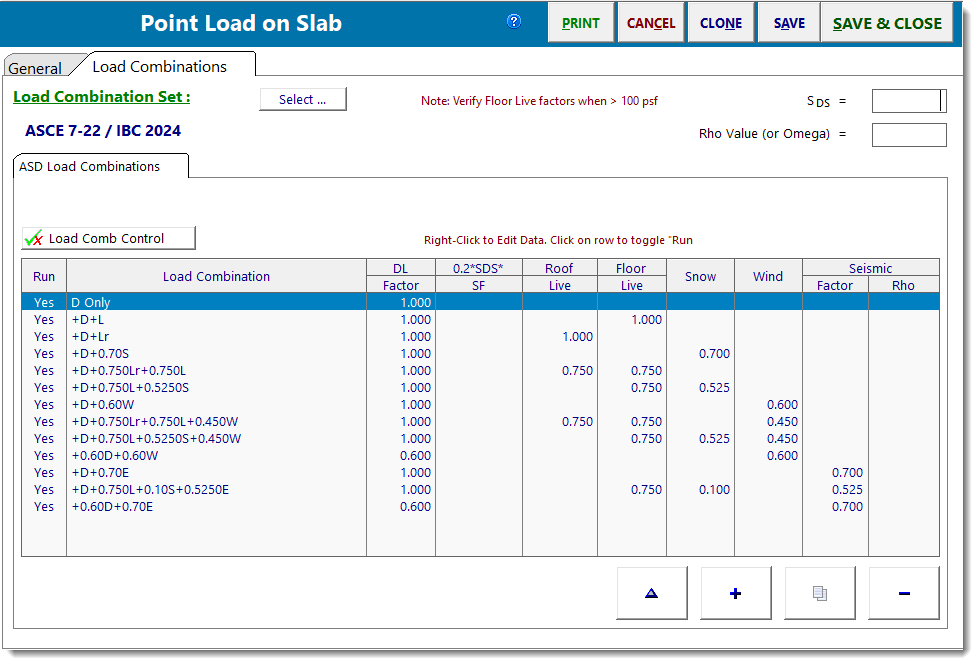
Load Combinations
This Load Combination set used is based on the selected design method, ASD or LRFD.
 <
<