Masonry Column |
  
|
Masonry Column |
|
This module designs masonry columns that are subject to axial loads and lateral bending loads about one axis.
The user can select ASD or LRFD methods.
All calculations are according to the ACI 530 or TMS 402, depending upon the selected design standard.
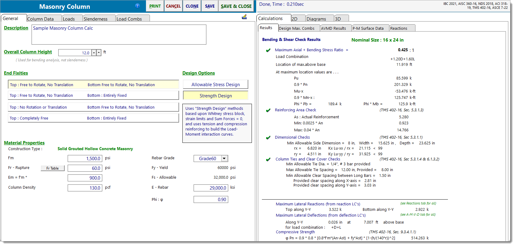
The screen capture below shows the full screen for masonry column design. See items below for descriptions of items that are specific to the masonry column design module.
For general description of the module, end fixity, loads, and load combinations click here. For slenderness description click here.
General
The area shown in the screen capture below is specific to the masonry column selection. You have the choice of using Working Stress or Strength Design methods.
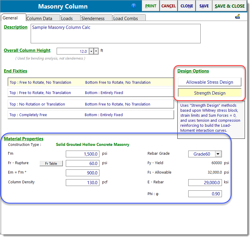
The design method is selected with the toggle shown above in the red bubble. Material properties are collected in the area shown in the blue bubble above.
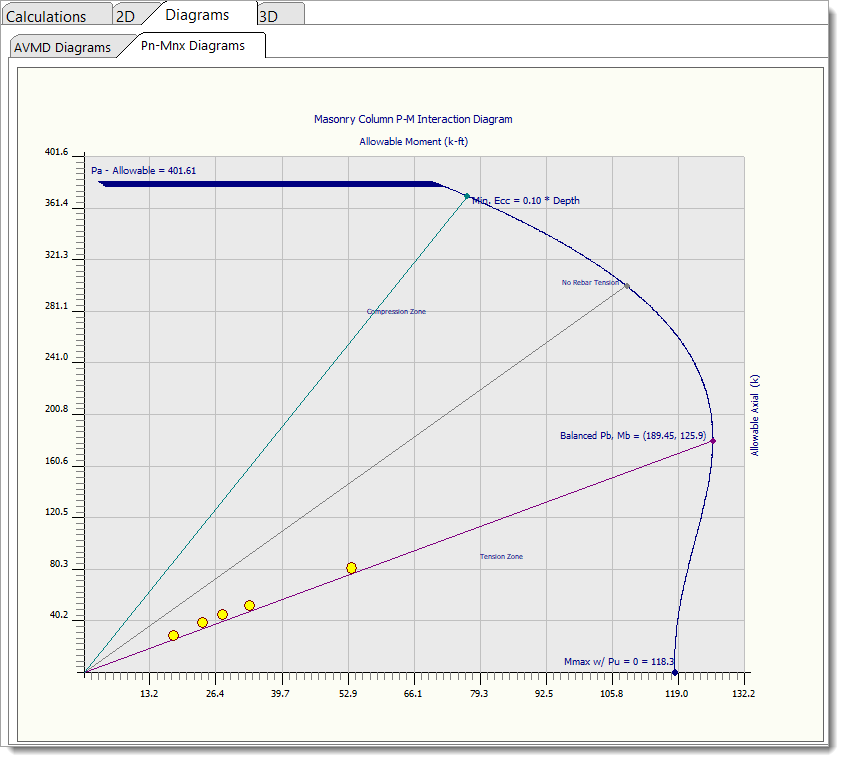
The column capacity is determined by creating a P-M interaction diagram, so that the effect of compressive force is included in the calculation of allowable moment capacity. For working stress this will result in significantly higher capacities than the older methods that calculated an actual stress ratio using (fa/Fa + fb/Fb).
Column Data
All of the information on this tab is specific to masonry column design.
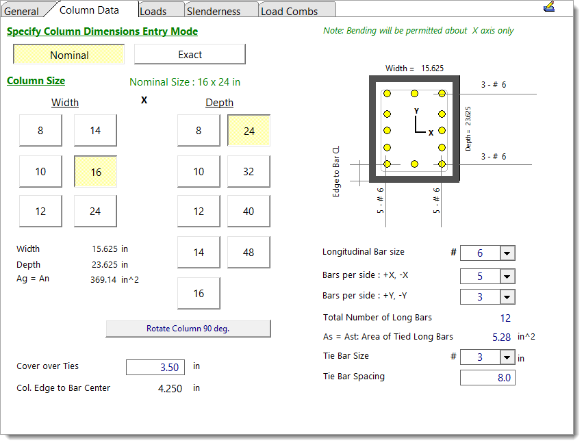
This tab collects the cross section size, reinforcing, and orientation of the column.
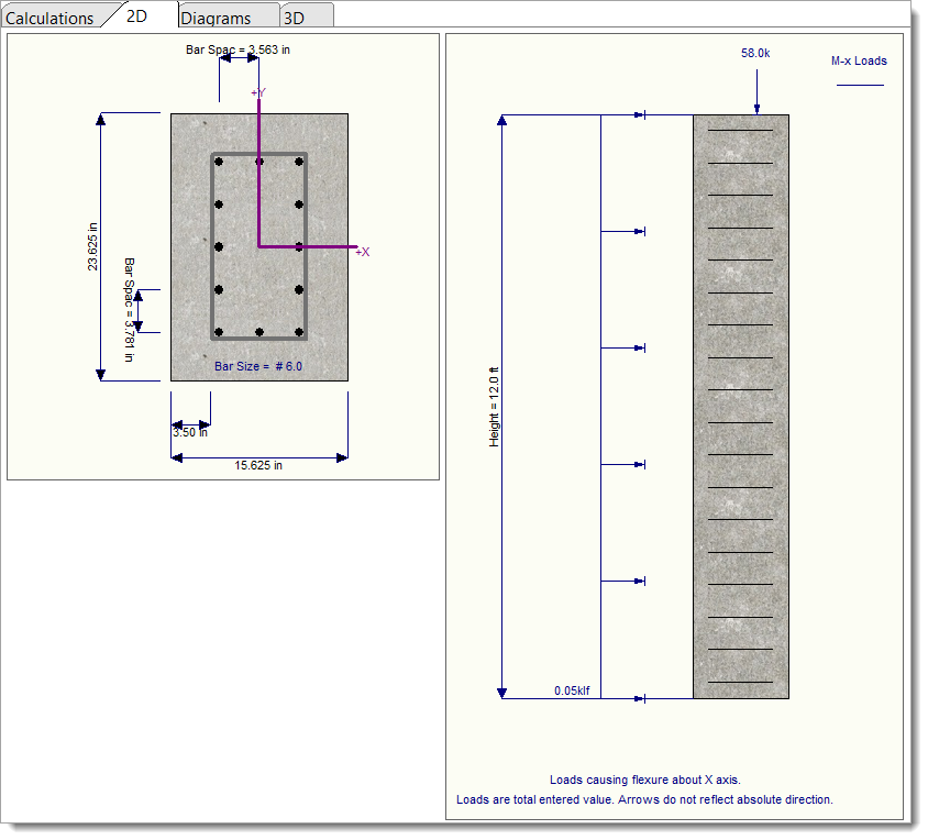
Section definition is made easy by buttons for the common nominal dimensions of a masonry column. Click the Width and Depth buttons and you will see the actual dimension appear in the bottom of the area. Note that "Width" is parallel to the "x-x" axis and "Depth" is parallel to the "y-y" axis.
To define the longitudinal reinforcement, use the "Bar Size" and "Bars per Side" drop-down menus. Bars on the "+X, -X" faces are placed parallel to the depth of the column (left and right sides in the cross-sectional view). Bars on the "+Y, -Y" faces are placed parallel to the width of the column (top and bottom sides in the cross-sectional view). The schematic graphic will change accordingly as your input changes. You can also use the 2D Sketch to see a scaled cross-sectional view of the column and to help verify that the reinforcement is defined correctly.
The calculation of the total area of laterally tied longitudinal reinforcing steel (Ast) assumes that the lateral tie detailing meets the requirements of TMS 402 §5.3.4.4(c), and therefore all defined bars will be included in the Ast calculation. Users must ensure that their column tie detailing aligns with these assumptions and/or confirm that this module is suitable for their specific design requirements. If the clear spacing between bars exceeds 6 inches, a warning will appear in the Results tab, reminding users to check their column tie detailing for compliance.
Loads
Load Reference Guide: Clicking this button opens a pop-up window that displays the positive sign conventions used in the module.
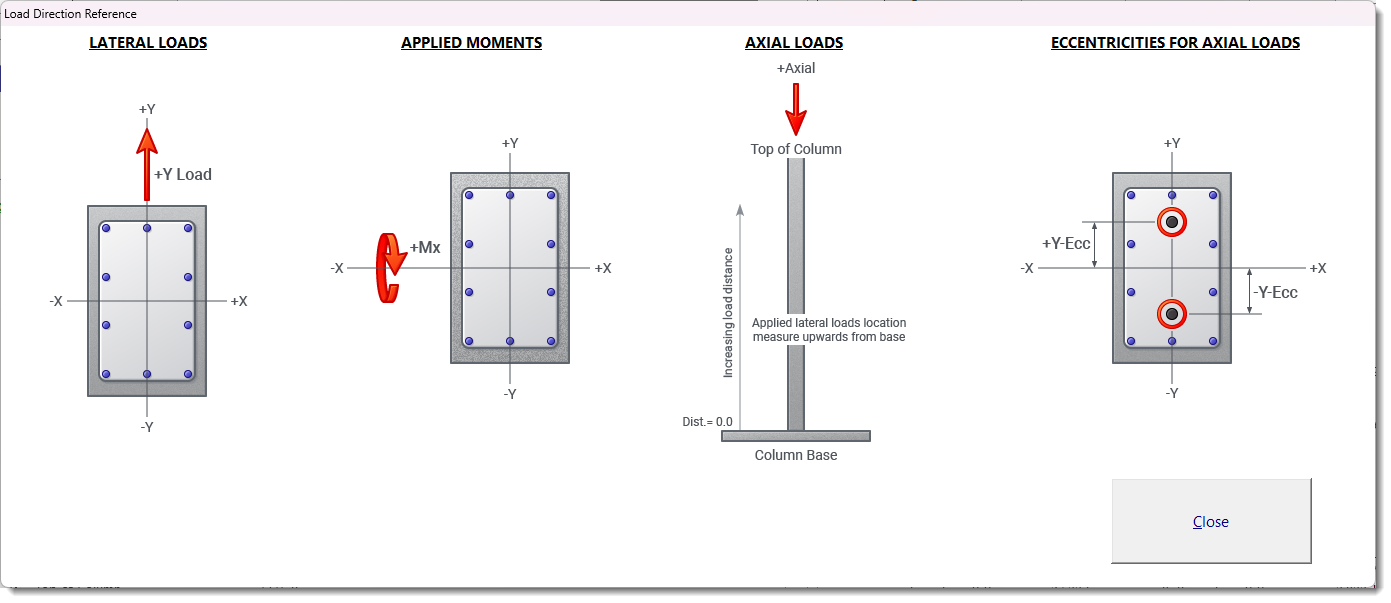
For more information on the Loads tab, please refer to the Columns topic.
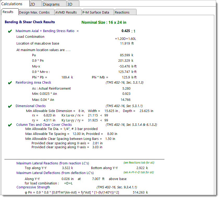
Results
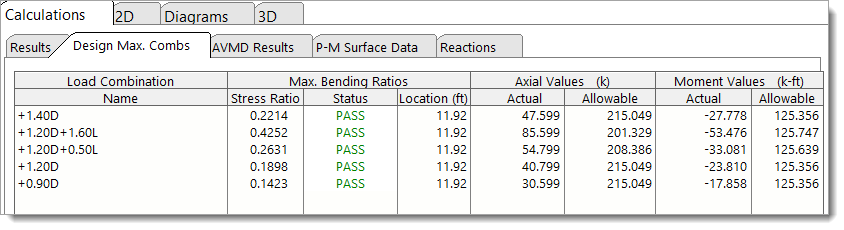
Design Maximum Combinations
This tab summarizes the maximum stress ratios for each load combination.
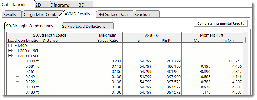
AVMD Results: SD/Strength Combinations
This tab presents the very detailed allowable and actual values for each load combination.
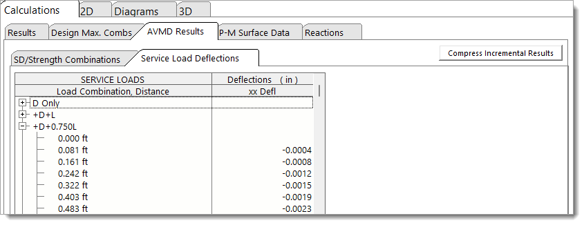
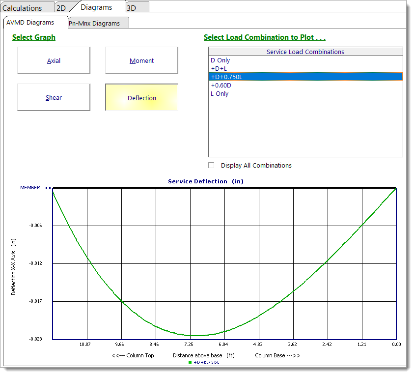
AVMD Results: Service Load Deflections
This tab summarizes the lateral deflections of the column at increments along its height. These values will be nonzero only if lateral loads are applied or the axial load is applied with an eccentricity.
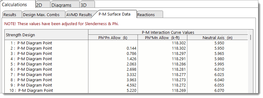
P-M Surface Data
This tab lists the full analysis results for the column.
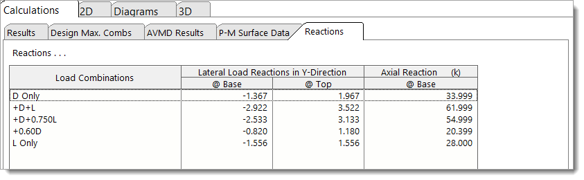
Reactions
This tab reports axial reactions and lateral reactions.
2D Sketch
AVMD Diagrams
Pn-Mnx Diagram
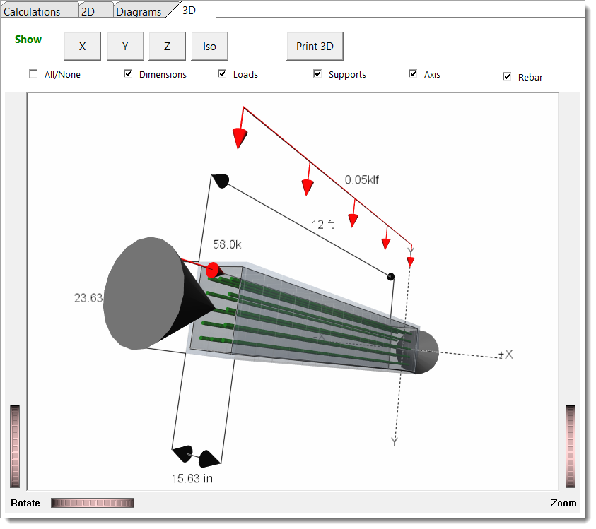
3D Rendering
 <
<