Concrete Beam |
  
|
Concrete Beam |
|
Last revised: Friday, May 22, 2026 at 03:21 PM
In this section, for each input tab we will review only the items that are unique to the CONCRETE material type.
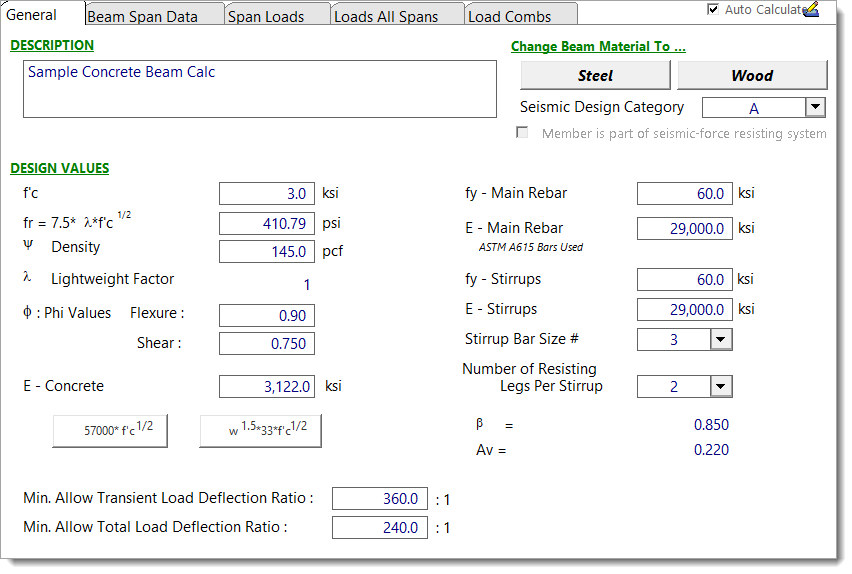
General
The concrete beam module handles single- and multiple-span (up to 8-span) beams using ONE cross section shape. That shape can have up to six groups of reinforcing per span, and the reinforcing can vary on a span-by-span basis.
This tab collects all the required rebar, concrete strength and elastic modulus entries, shear stirrup data, strength reduction factors and deflection criteria to check.
NOTE: It is important to know how this module operates with regard to beam stiffness along the span, and how this affects multi-span beams. This module divides each span into a series of segments. The effective moment of inertia for each segment (for each load combination) is calculated using the actual unfactored moment on that segment. Thus the module creates a very accurate variable stiffness model of the beam based on actual moments. For multiple-span beams, this will affect the relative stiffness of each beam span. Thus the moment distribution across multiple spans will be properly performed. This will affect factored load moments and shears and service load level deflections and reactions.
Seismic Design Categories and Concrete Beam Limitations
Concrete beams are subject to different requirements depending on the seismic design category (SDC) and whether they are part of the Seismic Force-Resisting System (SFRS). Below is a detailed explanation of how the Concrete Beam module handles each scenario:
Beam is part of the Seismic Force-Resisting System:
SDC |
Support |
ACI 318-19 Reference |
A |
No limitations. |
- |
B |
Results displayed with warning to refer to additional ACI requirements. |
Section 18.3 |
C |
Results displayed with warning to refer to additional ACI requirements. |
Section 18.4 |
D, E, F |
Results displayed with warning to refer to additional ACI requirements. |
Section 18.6 |
Beam is NOT part of the Seismic Force-Resisting System:
SDC |
Support |
ACI 318-19 Reference |
A, B, C |
No limitations. |
- |
D, E, F |
Results displayed with warning to refer to additional ACI requirements. |
Section 18.14 |
For scenarios where warnings are displayed, users must refer to the relevant ACI sections and ensure compliance separately as those additional requirements are outside the scope of this module.
Beam Span Data
This tab has some pieces of input that are constant for all spans and some that can vary on a span-by-span basis.
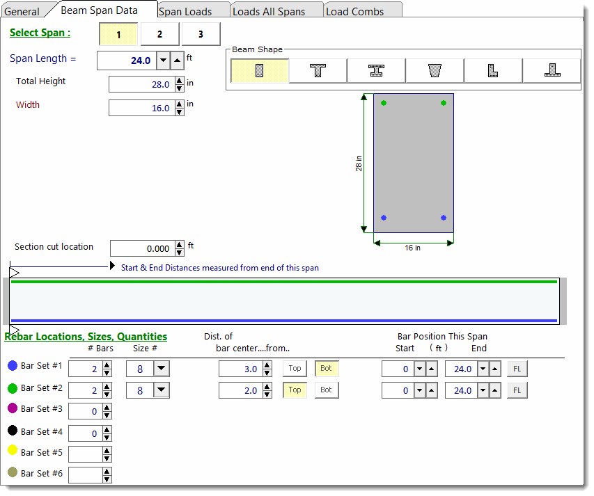
The cross section shape and dimensions are the same for all spans.
When you click on a span (for multi-span beams), the span length and rebar layout will update to display the arrangement that is specific to that span.
On the bottom of this tab you can specify up to 6 bar sets (quantity, size, vertical location and start/stop endpoints). Each bar set is referenced on the sketch with a color shown as a dot to the left of the set description.
The column titled "Dist of bar center....from...." is how you set the vertical position of the bar sets in the beam. When you look at the top one, you can read it as "The top bar set is 3 inches from the bottom of the beam". Note that the module will know whether the bars are in tension or compression and will handle the calculations properly.
The item labeled Bar Position This Span defines the starting and ending location of the bar ends with respect to the left end of each respective span. The data in the screen capture below shows that bar set #1 and #2 run from the left end (0.0 ft) to 24.0 ft from the left end of Span 1. Using these starting and ending locations you can fine tune the bar layout and end cutoffs.
NOTE: The module will report an error message if any beam segments are found to be completely unreinforced. Therefore, it is imperative that the rebar be defined in such a way as to prevent completely unreinforced segments. This includes the short segments at the extreme ends of a beam, where rebar is typically terminated. Remember that this module is an analysis tool, not a detailing tool, so don't be tempted to define rebar as starting or ending short of the physical end of the beam. The button labeled "FL" adjacent to each rebar definition has been provided as a convenient way to indicate to the program that the selected rebar runs the Full Length of the span.
IMPORTANT: In this module, rebar sets are assumed to be fully effective at the locations where they are defined. This means the reinforcement is considered fully developed at their defined start and end points, as reflected in the capacity diagram. Users must account for this behavior and ensure that any required additional rebar lengths are included in the construction drawings to achieve full development at the intended locations.
Span Loads
No differences from other materials.
All Span Loads
No differences from other materials.
Load Combinations
No differences from other materials.
Results Tabs
This set of tabs provides detailed results for the current calculation. The tabs in the upper right-hand corner of the screen allow you to select the four major areas available for review: Calculations, 2D Sketch, Diagram, and 3D Rendering.
Calculations
The Calculations tab offers the following results subtabs:
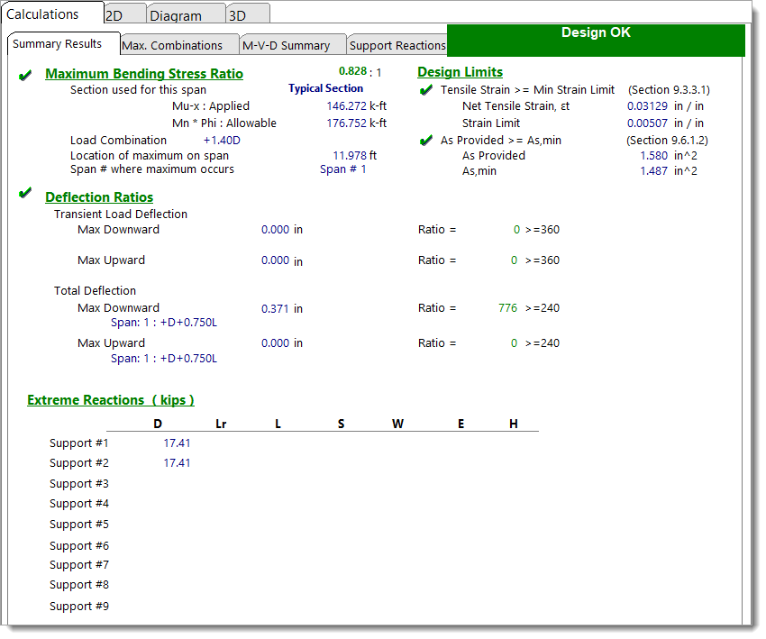
Summary Results provides details for shear, moment and deflection for the governing load combinations, as well as the governing prescriptive design limit checks required by the ACI. Shear results are not shown here. They are summarized on a separate tab that gives the required stirrup layout.
Depending on your beam configuration, related advisory messages may appear in the Summary Results tab. For example:
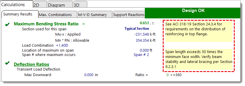
These checks are outside the scope of this module’s automated checks and must be verified by the user independently.
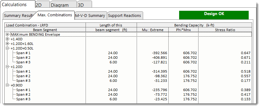
Max. Combinations provides detailed results for each beam segment for each load combination. These results are a consolidation to the highly detailed incremental results on the M-V-D Summary tab.
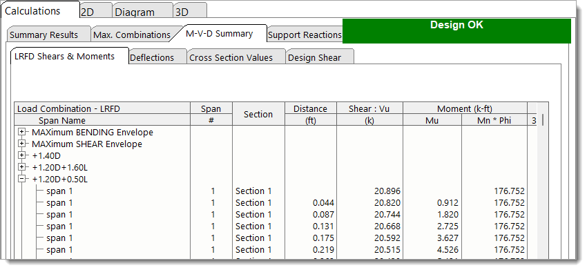
M-V-D Summary - LRFD Shears & Moments shows highly detailed moment and shear results for each beam and for each load combination. For multi-span beams using Automatic Unbalanced Live Load Placement there may be thousands of lines of results.
Minimum Steel Reinforcement Calculations (As,min)
Calculations for minimum steel reinforcement (As,min) are performed in accordance with ACI Sections 9.6.1.2 and 9.6.1.3 and reported accordingly:
1.The module evaluates equations (a) and (b) from ACI Section 9.6.1.2.
2.After determining the reinforcement ratio (ρ) required to meet flexural strength, the module checks Section 9.6.1.3 which specifies that the minimum steel area calculated from Section 9.6.1.2 does not need to exceed 4/3 of the As required for strength.
3.From these checks, the governing ρmin is identified, and the associated As,min value is determined and reported.
If the area of flexural reinforcement anywhere along the beam is less than As,min, the module will issue a warning letting you know to adjust the design.
Strain Limit Checks
This module calculates the net tensile strain, εt, at nominal strength to verify tension-controlled behavior in accordance with ACI 318 Section 9.3.3.1 and Table 21.2.2.
The net tensile strain limit is defined as:
Strain Limit = 0.004 [ACI 318-14 Section 9.3.3.1]
Strain Limit = εty + 0.003, where εty = fy / E [ACI 318-19 / 25 Section 9.3.3.1 and Table 21.2.2]
The net tensile strain, εt, is determined using a strain compatibility analysis of the cross section. This analysis is performed for each unique cross section with the top fiber in tension and with the bottom fiber in tension. The resulting values are also reported on the Cross Section Values tab.
M-V-D Summary - Deflections shows highly detailed deflection results for all load combinations. When each load combination is expanded by clicking the [+] icon, you will see the deflections along the entire beam. You will also see the effective moment of inertia used in that region. (Remember that the effective moment of inertia is calculated based on service-level moments at many locations along the length of each span.)
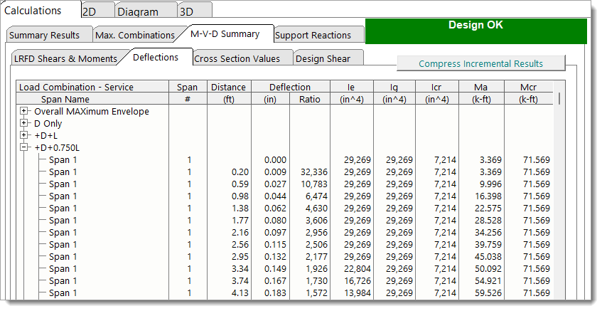
ACI 318-14: The module calculates Ie using Branson's formula as outlined in ACI 318-14 Equation 24.2.3.5(a), but with powers of 4 instead of 3:
The "fourth-power" version of Branson's formula, as recommended by ACI 435R-20, provides a more accurate representation of stiffness variations along the member for section-based analyses. In contrast, the "third-power" version in Equation 24.2.3.5(a) represents an averaged Ie over the full member length, which is not suitable for the section-based analysis performed by the Concrete Beam module.
ACI 318-19: The effective moment of inertia, Ie, is calculated based on ACI 318-19 Table 24.2.3.5:
|
|
|
|
M-V-D Summary - Cross Section Values shows the moment capacities and moment of inertia for all of the identified cross sections. The module has examined all of the spans you defined and looked for identical reinforcing layouts. It has eliminated the duplicates, and for simplicity, it only lists the unique reinforced cross sections here.

Steel Area for ρw reports the calculated values used to determine the tension reinforcement ratio () which is needed for calculating concrete shear capacity per Table 22.5.5.1.
As Top: Total area of tension reinforcement when the top of the beam is in tension. Taken as the sum of the areas of longitudinal bars located above the N.A. Dist value for "When Top in Tension" where N.A. Dist is measured from the bottom of the beam.
d Top: Distance from the bottom of the beam to the centroid of the bars included in "As Top".
As Bottom: Total area of tension reinforcement when the bottom of the beam is in tension. Taken as the sum of the areas of longitudinal bars located below the N.A. Dist value for "When Bottom in Tension" where N.A. Dist is measured from the top of the beam.
d Bottom: Distance from the top of the beam to the centroid of the bars included in "As Bottom".
The tension reinforcement ratio is then calculated as using either As Top and d Top or As Bottom and d Bottom, depending on the sign of the moment (Mu) at a given location along the beam.
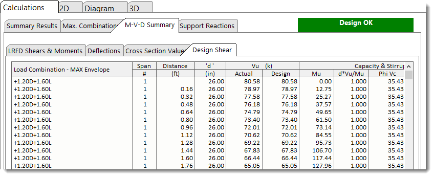
M-V-D Summary - Design Shear shows the shear stirrup requirements along the span(s) as required by the governing load combinations that generate the highest shear at each section.
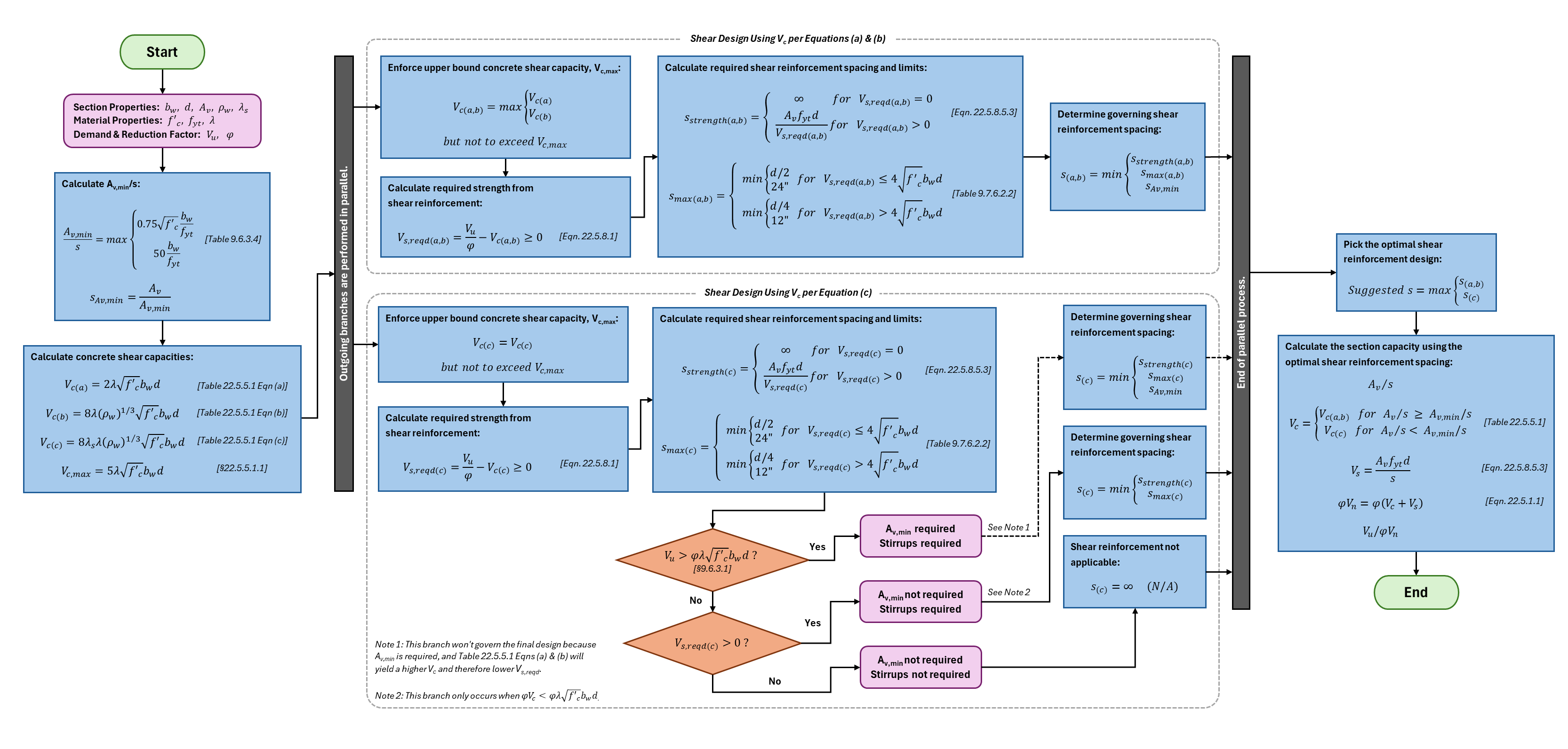
Shear Design Provisions for ACI 318-19 and beyond:
For ACI 318-19 and beyond, the provisions for determining nominal concrete shear strength () per §22.5.5.1 have been updated from previous versions of the ACI.
To select the appropriate equation for from Table 22.5.5.1, it is necessary to know the relationship between the provided area of shear reinforcement () and , where is calculated per §9.6.3.4 This creates a circular dependency since is needed to determine , but is required to calculate the nominal shear strength due to shear reinforcement () and the corresponding .
To address this circular logic, both scenarios outlined in Table 22.5.5.1 are evaluated by calculating using equations (a, b) and (c). The required stirrup layout for each scenario is then determined, and the layout that produces the most favorable results is reported. Note, the Concrete Beam module only enforces where per §9.6.3.1.
This logic is outlined in the flowchart below:
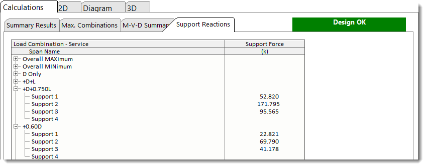
Support Reactions shows reactions for each support for each load condition.
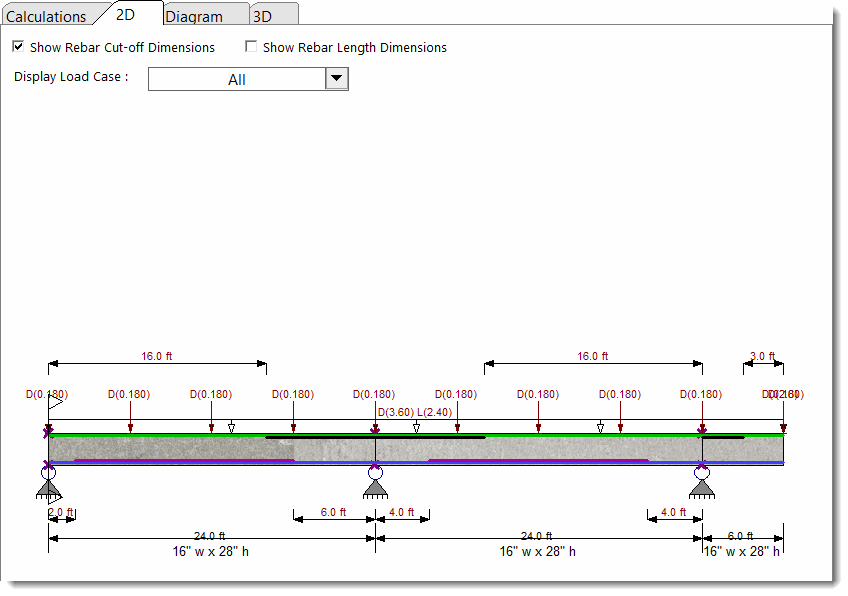
2D Sketch
The 2D Sketch tab provides a graphic representation of the beam currently being designed:
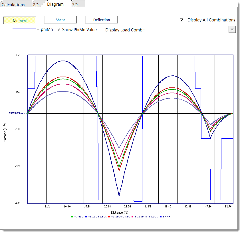
Diagram
The Diagram tab offers the ability to view shear, moment, and deflection diagrams for selected load combinations, as well as a moment envelope:
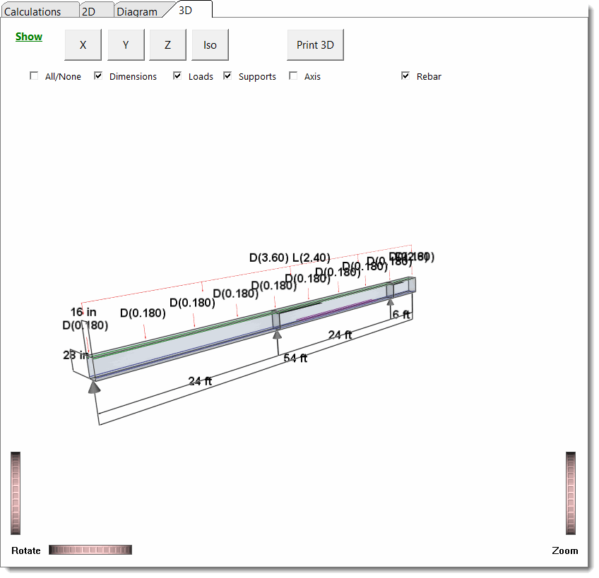
3D Rendering
The 3D Rendering tab offers a 3D view of the beam, with controls to display options:
 <
<