Concrete Shear Wall |
  
|
Concrete Shear Wall |
|
Last revised: Thursday, January 29, 2026 at 02:40 PM
This module allows the design of concrete shear walls per ACI 318 Chapter 11 including multi-story walls with no openings but with up to five levels of differing length, height and thickness.
NOTE: As of February 2025, the Concrete Shear Module supports defining horizontal and vertical reinforcement for walls designed per ACI 318-19 and later. The module will check shear strength as well as prescriptive ACI reinforcement limits and detailing requirements based on the defined layout. When opening a calculation created before this update, a prompt will appear to review the Story Data tab and define the reinforcement layout.
Additionally, based on discussions with industry experts about the interpretation of the 'hw' and 'Lw' values when calculating 'αc', this module no longer allows varying wall lengths on a story-by-story basis. Wall lengths and offsets are now standardized across all stories. The shear wall aspect ratio Hw/Lw is now calculated using the global dimensions of the entire wall stack. When opening older Concrete Shear Wall calculations, a warning message will highlight these changes. If needed, legacy calculation data remains accessible in previous builds.
General
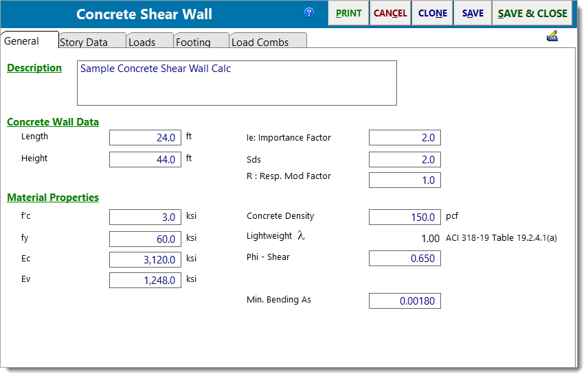
Length specifies the total length of the wall.
Height specifies the total height of the wall. On the next tab you can divide that total height into up to five different wall portions.
f'c is the concrete strength.
fy is the yield stress of rebar.
Ec is the bending modulus of elasticity.
Ev is the shear modulus of elasticity.
Ie, Sds, and R are used to calculate the in-plane portion of the wall weight to be applied as a seismic load.
Concrete Density is the unit weight of concrete in pounds per cubic foot (pcf).
Lightweight λ is for lightweight concrete and as calculated based on Concrete Density per ACI 318-19 Table 19.2.4.1(a).
Phi - Shear is the strength reduction factor used for shear calculations. Refer to ACI 318-19 Table 21.2.1 and section 21.2.4 for modifications pertaining to seismic force resisting elements.
Min. Bending As is the minimum required flexural reinforcement ratio.
Default Rebar Sizes & Spacing (ACI 318-14 only): specify size, spacing, and cover for horizontal and vertical rebar. These inputs are used for drawing the graphics to scale, as well as for determining limiting reinforcing percentages.
Story Data
This tab is where you specify the distinct wall levels for the wall.
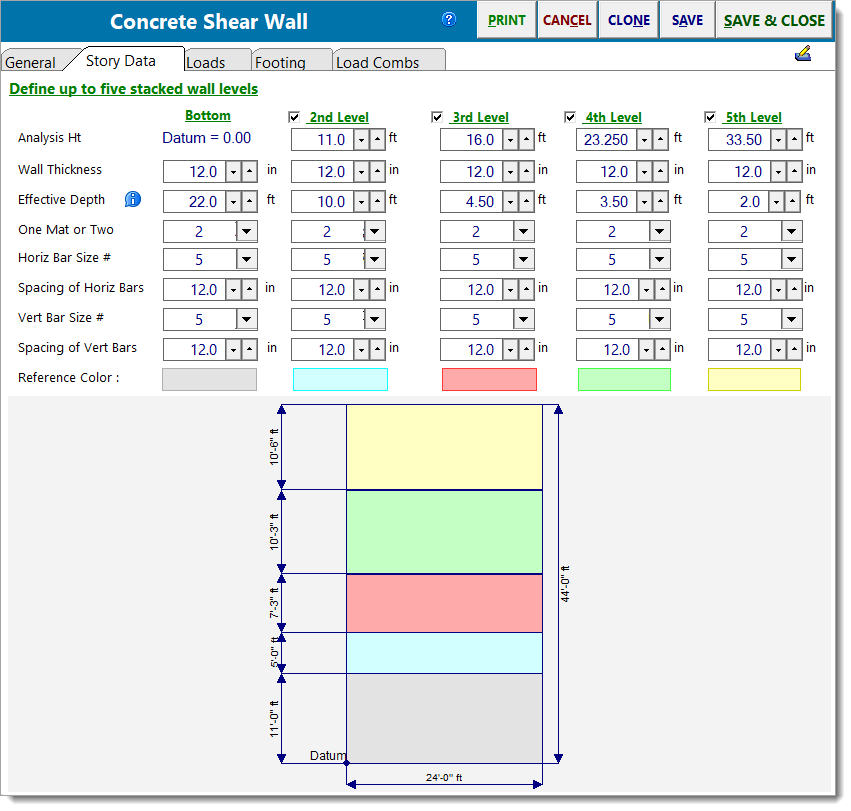
Analysis Height locates the bottom edge of the wall section and is where the maximum shear and bending stress will be calculated. This is the user-defined height at which the analysis of a particular wall section will be performed. All moments, shears, and vertical loads at this height will be calculated using all applied lateral and vertical loads and the wall self weight above this point. The other wall data items specified in the same column will be used between this analysis height and the next higher level indicated in the column to the right.
ALWAYS DEFINE ANALYSIS HEIGHTS IN INCREASING ORDER FROM LEFT TO RIGHT. This is needed due to the manner in which the module calculates the heights by comparing heights of adjacent sections.
Wall thickness is the thickness of this wall section. Enter the thickness to be used in the analysis of a particular wall section. This thickness will be used only between the Analysis Height for that section up to the analysis of the next higher section (or Total Wall Height if it is the highest section).
Effective Depth locates the tension reinforcement within the panel. For designs following ACI 318-14, it is also used to calculate the shear depth, which is required for determining actual shear stresses. Similar to beams, the Effective Depth is measured from the wall’s compression edge to the centroid of the tension chord reinforcement.
Reference Color provides a visual reference color to each wall section for easy identification in the graphical sketch.
The following controls are only available for ACI 318-19 and up:
One Mat or Two specifies whether the reinforcement consists of a single layer or two layers of both horizontal and vertical reinforcement.
Horiz Bar Size # defines the size of the horizontal reinforcement bars in the shear wall, using standard rebar designations (e.g., #5, #6, etc.).
Spacing of Horiz Bars defines the center-to-center spacing of the horizontal reinforcement bars in inches.
Vert Bar Size # defines the size of the vertical reinforcement bars in the shear wall, using standard rebar designations (e.g., #5, #6, etc.).
Note: The vertical reinforcement specified here is only used for the prescriptive reinforcement limits and detailing checks per ACI 318 Chapter 11. It is not utilized for flexural reinforcement. The required flexural reinforcement is reported separately on the Summary tab as "Bending As Req’d".
Spacing of Vert Bars defines the center-to-center spacing of the vertical reinforcement bars in inches.
Loads
This main tab has four sub-tabs that allow you to enter four types of loads.
Vertical loads can be of dead, live, roof live and snow types.
Lateral loads can be of seismic and wind types.
Add wall weight to dead loads will tell the module to calculate the weight of the wall above each analysis height and include it in the vertical dead loads to calculate applied axial stress. It also is used for footing design when that option is selected.
Add wall weight as SEISMIC load will calculate the wall self weight, apply the lateral weight seismic factor and "E" load combination factor. The resulting load will be applied at the wall center to calculate shear and overturning due to that portion of the wall. This is used for values at the analysis height, for the effect of that level's seismic weight on the levels below, and for footing overturning and sliding calculations.
Vertical Point Loads
Use this tab to apply point loads to the wall. You can specify an "X" and "Y" distance from the lower-left corner of the lower wall so that the load can be located anywhere on the defined walls.
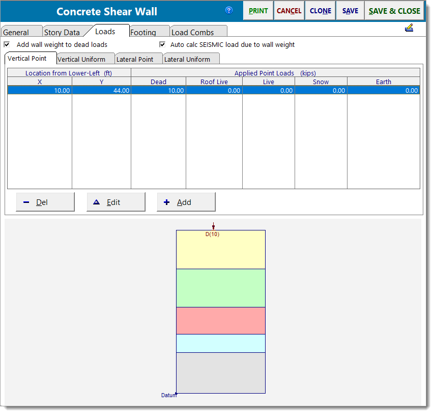
Use the [Add] and [Edit] buttons to change the values of applied loads. Clicking either button displays this window:
Vertical Uniform Loads
Use this tab to apply uniform loads to the wall. You can specify a "Y" distance from the bottom of the lower wall so that the load can be located at any height.
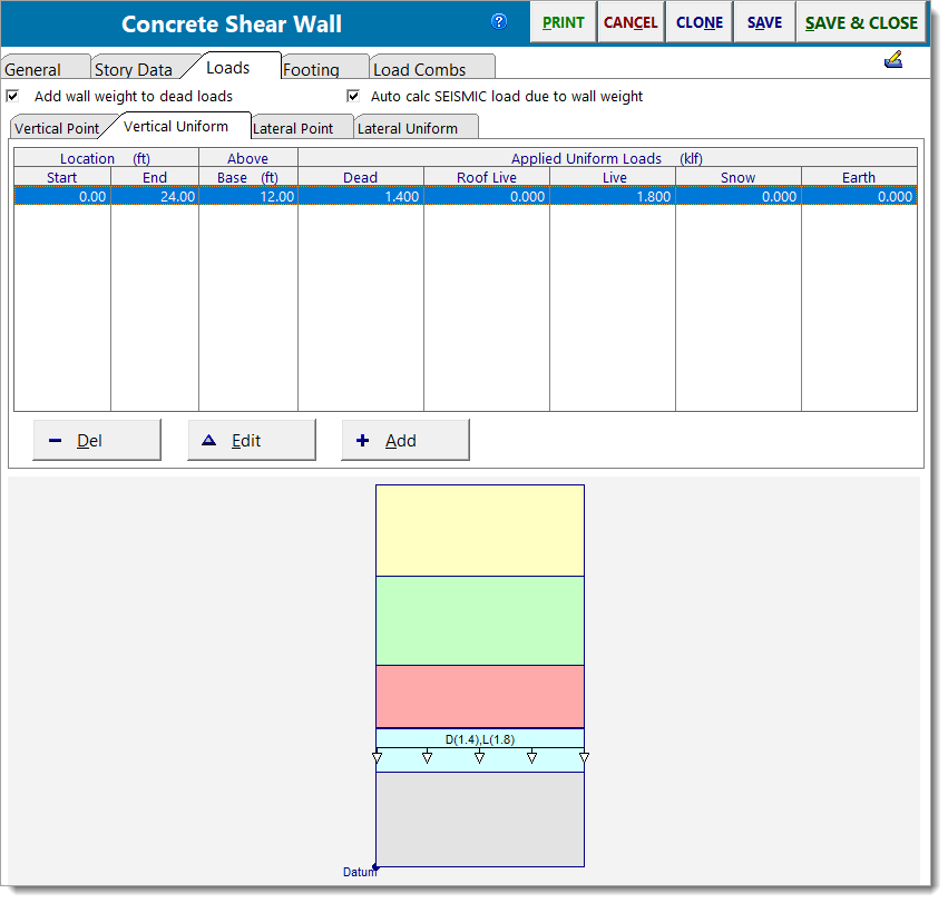
Use the [Add] and [Edit] buttons to change the values of applied loads. Clicking either button displays this window:
Lateral Point Loads
Use this tab to apply point lateral loads to the wall. You can specify a "Y" distance from the bottom of the lower wall so that the load can be located at any height.
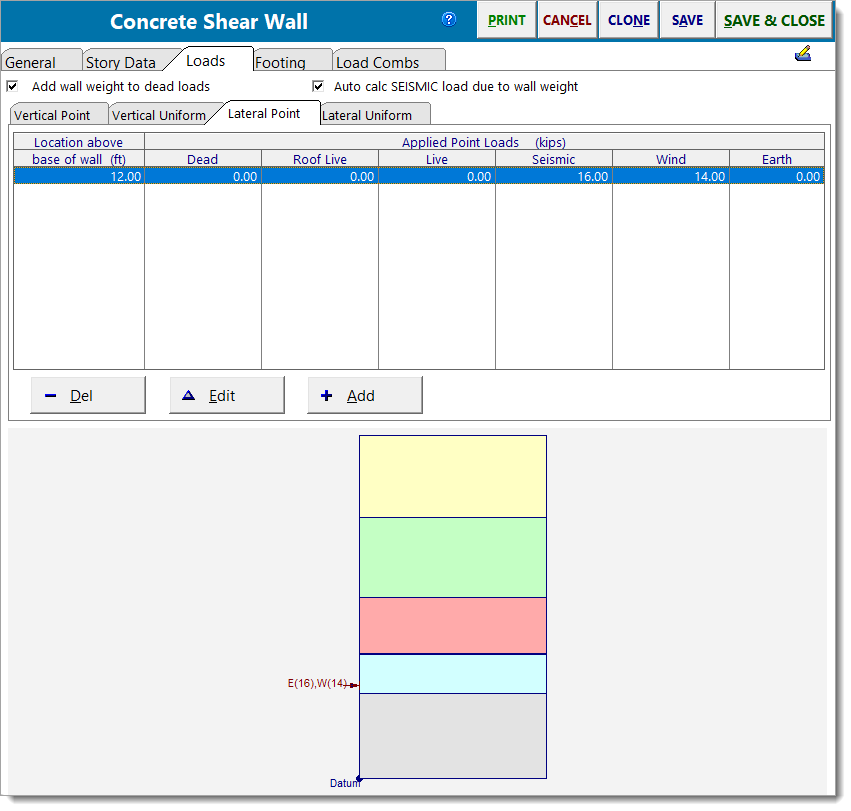
Use the [Add] and [Edit] buttons to change the values of applied loads. Clicking either button displays this window:
Lateral Uniform Loads
| Use this tab to apply uniform lateral loads to the wall. You can specify a Start and End location to define the extent of the lateral load. |

Use the [Add] and [Edit] buttons to change the values of applied loads. Clicking either button displays this window:
Footing
Optional tab to design a footing that behaves as a continuous grade beam that cantilevers past the end of the wall.
Specify geometry, allowable soil pressure, and material properties to arrive at checks for soil pressure and footing flexure.
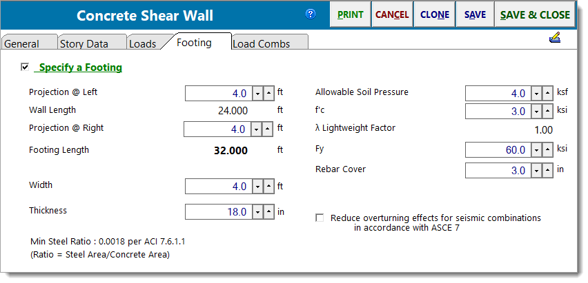
Specify a Footing: If this checkbox is selected, then the input fields for defining a footing are displayed. Note: This checkbox also causes some footing-related input to be shown or hidden as appropriate on the Loads tab.
Projection @ Left: Enter the projection of the footing beyond the left end of the wall in units of ft.
Wall Length: The program reports the shear wall length in units of ft for reference.
Projection @ Right: Enter the projection of the footing beyond the right end of the wall in units of ft.
Footing Length: The program reports the footing length in units of ft for reference.
Width: Specify the width of the footing in units of ft. This is the dimension perpendicular to the wall length.
Thickness: Enter the thickness of the footing in units of inches.
Min Steel Reinforcing: The minimum flexural reinforcement ratio, per ACI 7.6.1.1, is 0.0018 times the gross area of the concrete (Width x Thickness). Commentary R7.6.1.1 also notes that minimum flexural reinforcement should be placed as close as possible to the tension face of the concrete, unlike shrinkage and temperature reinforcement which may be distributed between the top and bottom faces of the footing.
Allowable Soil Pressure: Specify the allowable soil bearing pressure in units of ksf.
f'c: Specify the compressive stress of concrete in units of ksi.
Fy: Specify the yield stress of rebar in units of ksi.
Rebar Cover: Specify the cover over rebar in units of inches. The program will use this value and a 1/2" allowance for the rebar size to calculate the effective depth of the concrete section.
Note: Rebar is assumed to exist only at the bottom of the footing to resist tensile forces from the vertical loads and increased pressure due to overturning forces. Tension in the top of the footing in cases where no upward soil pressure exists and the footing weight creates a downward net force IS IGNORED.
Reduce overturning effects for seismic combinations per ASCE 7-16 Section 12.13.4: Applies the referenced reduction in overturning force for seismic load combinations when selected.
Load Combinations
The typical load combination tab for strength design of concrete is provided.
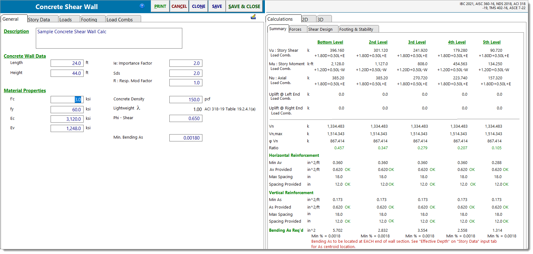
Summary
Provides a summary of each level.
In the top portion of the window, you will see the following:
Specify a Footing: If this checkbox is selected, then the input fields for defining a footing are displayed. Note: This checkbox also causes some footing-related input to be shown or hidden as appropriate on the Loads tab.
Projection @ Left: Enter the projection of the footing beyond the left end of the wall in units of ft.
Vu: Story Shear: The governing shear force and associated load combination at each level.
Mu: Story Moment: The governing flexural moment and associated load combination at each level.
Nu: Axial: The governing axial demand and associated load combination at each level.
Uplift @ Left End / Right End: The net uplift force at the left and right ends of the wall due to overturning moments from lateral loads and vertical loads. The centroid location for the net uplift is determined by the "Effective Depth" specified in the "Story Data" tab.
In the bottom portion of the screen, the content displayed varies depending on the governing ACI edition.
ACI 318-14 only: Shear strength, horizontal steel, vertical steel, and end reinforcing for bending tension in that wall section are reported.
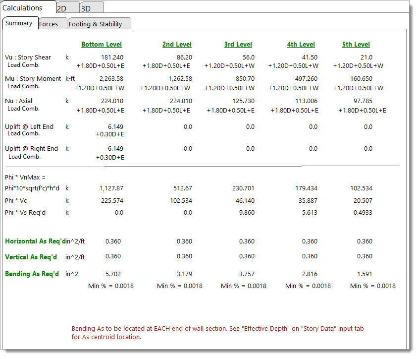
Phi * 10 * sqrt(f'c) * h * d: The maximum nominal shear strength of the wall section per ACI 318-14 Section 11.5.4.3.
Phi * Vc: The shear contribution from concrete alone per ACI 318-14 Section 11.5.4.5 or Table 11.5.4.6 if the "Detailed" method is enabled on the General tab..
Phi * Vs Req'd: The shear contribution required from reinforcement to resist applied shear forces per ACI 318-14 Eqn. 11.5.4.4 and Eqn. 11.5.4.8.
Horizontal As Req'd: The required horizontal reinforcement area per unit length of the wall (in²/ft).
Vertical As Req'd: The required vertical reinforcement area per unit length of the wall (in²/ft). Note: This is used only for prescriptive detailing per ACI 318 Chapter 11, not for flexural reinforcement.
Bending As Req'd: The total required flexural reinforcement area (in²) at each level. This reinforcement must be placed at each end of the wall section. The centroid location for this reinforcement is determined by the "Effective Depth" specified in the "Story Data" tab.
ACI 318-19 only: Shear strength, horizontal steel area and spacing, vertical steel area and spacing, and end reinforcing for bending tension in that wall section are reported.
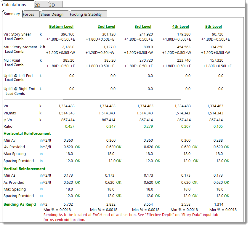
Shear Strength (Vn, Vn,max, φVn, Ratio): This section reports the governing shear strength demand-capacity ratio due to the applied shear force, as well as the associated shear strengths. More detail is provided in the description for the "Shear Design" tab below.
Horizontal/Vertical Reinforcement: This section summarizes the governing horizontal and vertical reinforcement checks, including minimum reinforcement checks per ACI 318-19 Section 11.6 and maximum bar spacing limits per Section 11.7. Detailed explanations can be found in the "Shear Design" tab description below.
Bending As Req'd: The total required flexural reinforcement area (in²) at each level. This reinforcement must be placed at each end of the wall section. The centroid location for this reinforcement is determined by the "Effective Depth" specified in the "Story Data" tab.
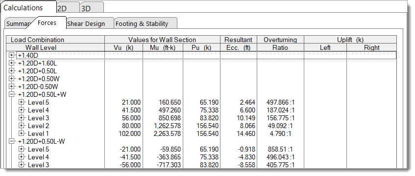
Forces
This tab provides the detailed force values for each wall level and for each load combination.
Shear Design
This tab provides the detailed shear design results for each wall level and for each load combination. This tab is only visible for ACI 318-19 and above.
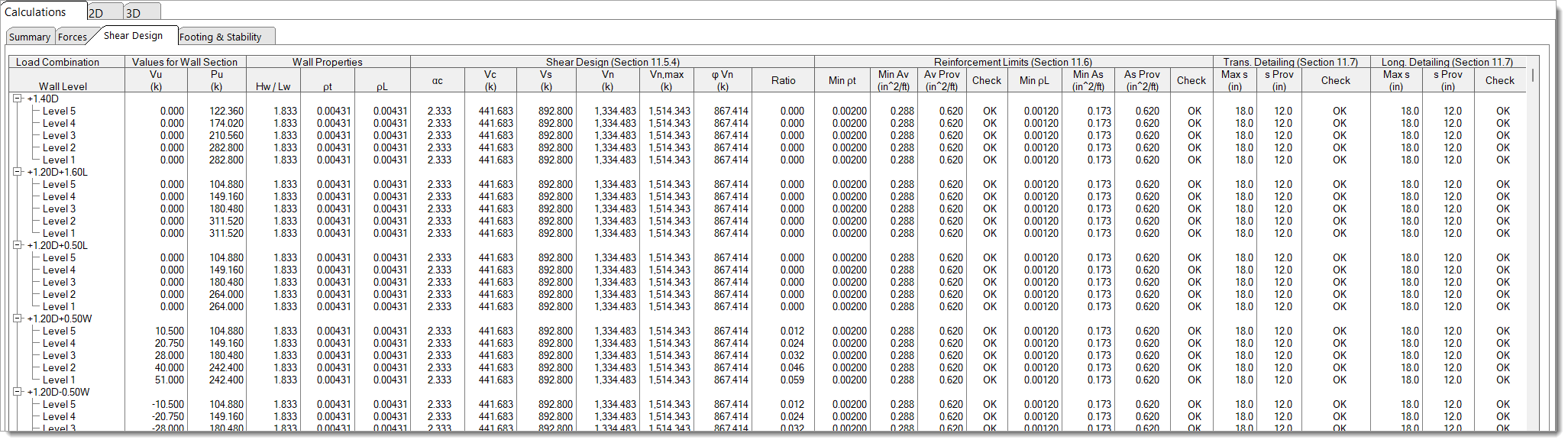
Values for Wall Section
Vu (k): The applied shear force at each wall level under the given load combination.
Pu (k): The applied axial force at each wall level due to vertical loads.
Wall Properties
Hw/Lw: The wall aspect ratio of the entire wall stack.
pt: The total transverse (horizontal) reinforcement ratio in the wall.
pL: The total longitudinal (vertical) reinforcement ratio in the wall.
Shear Design (Section 11.5.4)
αc: Coefficient for the relative contribution of concrete strength to nominal wall shear strength, calculated per ACI 318-19 Section 11.5.4.3.
Vc (k): The shear strength provided by the concrete alone, calculated as per ACI 318-19 Eqn. 11.5.4.3.
Vs (k): The shear strength provided by the defined horizontal reinforcement, calculated as per ACI 318-19 Eqn. 11.5.4.3.
Vn (k): The total nominal shear strength, which is the sum of Vc and Vs per ACI 318-19 Eqn. 11.5.4.3.
Vn,max (k): The maximum allowable nominal shear strength for the wall section, calculated as per ACI 318-19 Section 11.5.4.2.
φVn (k): The total factored shear strength, taken as φ times the minimum of Vn and Vn,max.
Ratio: The ratio of applied shear force Vu to factored shear strength φVn. A value of 1.0 or less indicates the wall is adequate for shear.
Reinforcement Limits (Section 11.6)
Min pt: The minimum required transverse (horizontal) reinforcement ratio to satisfy prescriptive reinforcement detailing requirements per ACI 318-19 Section 11.6.
Min Av (in²/ft): The minimum required area of horizontal reinforcement per unit length of the wall, calculated as [Min pt] * [Wall Thickness] * 12".
Av Prov (in²/ft): The provided horizontal reinforcement area per unit length.
Check: Indicates whether the provided horizontal reinforcement meets the prescriptive reinforcement limits.
Min pL: The minimum required longitudinal (vertical) reinforcement ratio to satisfy prescriptive reinforcement detailing requirements per ACI 318-19 Section 11.6.
Min As (in²/ft): The minimum required vertical reinforcement per unit length of the wall, calculated as [Min pL] * [Wall Thickness] * 12".
As Prov (in²/ft): The provided vertical reinforcement per unit length.
Check: Indicates whether the provided vertical reinforcement meets the prescriptive reinforcement limits.
Transverse Detailing (Section 11.7)
Max s (in): The maximum allowable spacing for transverse (horizontal) reinforcement per ACI 318-19 Section 11.7.3.
s Prov (in): The provided spacing of horizontal reinforcement.
Check: Indicates whether the provided spacing meets prescriptive reinforcement detailing requirements.
Longitudinal Detailing (Section 11.7)
Max s (in): The maximum allowable spacing for longitudinal (vertical) reinforcement per ACI 318-19 Section 11.7.2.
s Prov (in): The provided spacing of vertical reinforcement.
Check: Indicates whether the provided spacing meets prescriptive reinforcement detailing requirements.
Footing & Stability
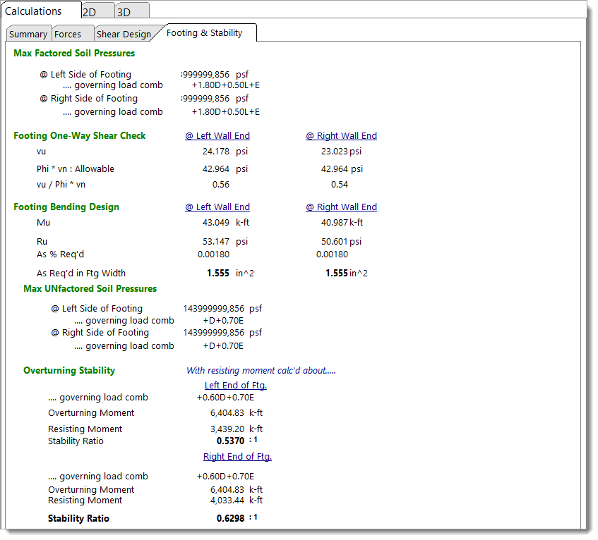
Footing Design Combination Pressures: Reports the maximum factored soil pressures at the left and right sides of the footing, along with the load combination responsible for producing each of those pressures. These are used in the reinforced concrete design calculations for the footing.
Footing One-Way Shear Check: Reports the calculated one-way shear at both ends of the footing.
For footings designed per ACI 318-14 and earlier, and ACI 318-25 and later:
The nominal shear strength follows the one-way shear provisions of ACI 318-14 §22.5.5.1 / ACI 318-25 §13.2.6.2:
φ vn = φ * 2 * λ * √(f'c), where φ = 0.75.
For footings designed per ACI 318-19:
The nominal shear strength follows the one-way shear provisions of §22.5 and Table 22.5.5.1 (referenced by §7.5.3.1):
φ vn = φ * 8 * λs * λ * (ρw)1/3 * √(f'c), where φ = 0.75.
Note: The one-way shear capacity assumes no transverse reinforcement in the footing. Therefore, Av < Av,min, and equations (a) and (b) from Table 22.5.5.1 are not applicable.
It is also acceptable to neglect the size effect factor (λs) for one-way shallow foundations per §13.2.6.3, so λs = 1.0.
This value is also subject to additional limits per §22.5.5.1.1:
Lower bound: φ * λ * √(f'c)
Upper bound: φ * 5 * λ * √(f'c)
Footing Bending Design: Reports the results of the flexural analysis and design including recommended reinforcing options to satisfy the required area of steel.
Soil Pressure Combination Pressures: Reports the maximum unfactored soil pressures at the left and right sides of the footing, along with the load combination responsible for producing each of those pressures. Unfactored soil pressures are compared to the allowable soil bearing pressure provided by the user.
Overturning Stability: Reports the overturning analysis performed about each end of the footing including the overturning moment, the resisting moment, the stability ratio, and the governing load combination.
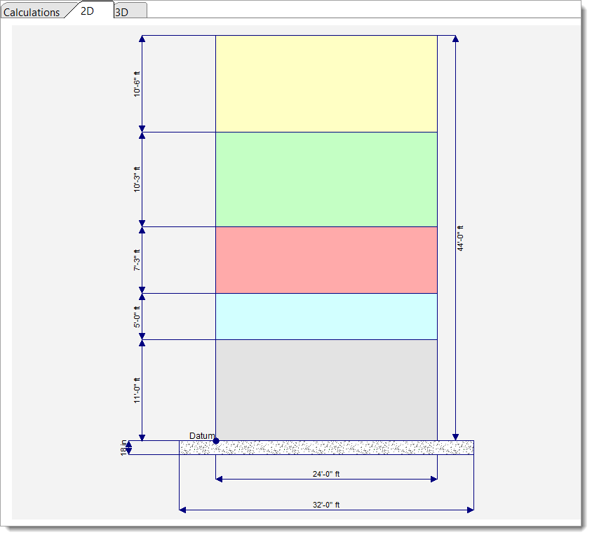
2D Sketch
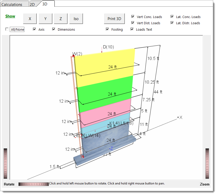
3D Rendering
 <
<