General |
  
|
General |
|
Last revised: Thursday, January 29, 2026 at 02:36 PM
The General tab is where you can define the model description, analysis method, global Y load sign behavior, and gives a live schematic of the frame.
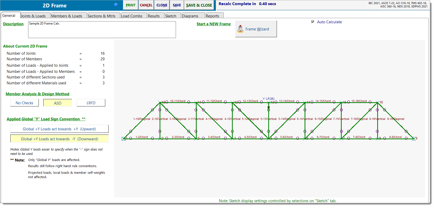
Description: Free-text label for the calculation. This name appears in the Project Manager and on printed reports.
About Current 2D Frame: A read-only snapshot of the current model, including:
•Number of joints
•Number of members
•Number of joint loads
•Number of member loads
•Number of unique sections
•Number of unique materials
Member Analysis & Design Method: Select the design method for how members are checked. The selected method applies to all applicable members in the frame.
•No Checks: Analysis only. No code checks.
•ASD: Allowable Stress Design.
•LRFD: Load and Resistance Factor Design.
Applied Global "Y" Load Sign Convention: Controls how Global Y loads are interpreted when entered:
•Global +Y loads act towards +Y (Upward): Global +Y loads are applied in the upward direction, consistent with the global positive Y-axis.
•Global +Y loads act towards -Y (Downward): Global +Y loads are applied in the downward direction, aligned with gravity. This option can simplify the entry of gravity loads by removing the need to manually apply a negative sign for downward forces.
Note:
oThis setting only affects applied Global Y loads. Local loads, projected loads, and self-weight are not affected.
oAnalysis results continue to follow standard right-hand rule sign conventions.
oReported reactions still align with the global +Y convention, meaning a downward load produces a positive +Y reaction, while an upward load produces a -Y reaction.
Frame Wizard: The Frame Wizard can create complete 2D Frame models for many typical framing configurations and truss layouts with just a few simple inputs.
Auto Calculate: When enabled, the frame recalculates automatically after changes. When disabled, recalculation must be triggered manually.
 <
<