Assigning Proper Fixities |
  
|
Assigning Proper Fixities |
|
Last revised: Monday, December 22, 2025 at 11:28 AM
When working with truss models with pinned joints, consider setting the following Joint Boundary Restraints:
Joint |
X Translation |
Y Translation |
Z Rotation |
Notes |
|---|---|---|---|---|
Typical |
Unrestrained |
Unrestrained |
Restrained |
Although rotation at the joints is restrained, moment transfer is prevented by member end releases. |
Support 1 |
Restrained |
Restrained |
Restrained |
|
Support 2 |
Unrestrained |
Restrained |
Restrained |
Even though the support joints are modeled as Restrained against rotation, all members framing into those joints will have their Local z Rotational degree of freedom released at both ends, so no moment will be delivered to the supports from the members.
There must be at least two "support joints" to create global stability of the entire truss. Typically, we see two support joints with Y translational restraints and one support joint with X translational restraint, but many conditions are possible.
Next, consider the following settings the Member End Releases:
Member Ends |
Local x Translation |
Local y Translation |
Local z Rotation |
Notes |
|---|---|---|---|---|
Typical |
Unreleased |
Unreleased |
Released |
Members are hinged at the joints. |
When working with portal frames with moment connected joints and fixed bases, consider setting the following Joint Boundary Restraints:
Joint |
X Translation |
Y Translation |
Z Rotation |
Notes |
|---|---|---|---|---|
Typical |
Unrestrained |
Unrestrained |
Unrestrained |
Allows joints to freely move in X and Y and rotate about Z. |
Supports |
Restrained |
Restrained |
Restrained |
Fixed base. |
Consider the following settings the Member End Releases:
Member Ends |
Local x Translation |
Local y Translation |
Local z Rotation |
Notes |
|---|---|---|---|---|
Typical |
Unreleased |
Unreleased |
Unreleased |
Members are continuous through the joints. |
When working with portal frames with moment connected joints and pinned bases, consider setting the following Joint Boundary Restraints:
Joint |
X Translation |
Y Translation |
Z Rotation |
Notes |
|---|---|---|---|---|
Typical |
Unrestrained |
Unrestrained |
Unrestrained |
Allows joints to freely move in X and Y and rotate about Z. |
Supports |
Restrained |
Restrained |
Unrestrained |
Pinned base. |
Consider the following settings the Member End Releases:
Member Ends |
Local x Translation |
Local y Translation |
Local z Rotation |
Notes |
|---|---|---|---|---|
Typical |
Unreleased |
Unreleased |
Unreleased |
Members are continuous through the joints. |
When working with models with a mix of fixity conditions, consider setting the following Joint Boundary Restraints:
Joint |
X Translation |
Y Translation |
Z Rotation |
Notes |
|---|---|---|---|---|
Typical |
Unrestrained |
Unrestrained |
Unrestrained |
Allows joints to freely move in X and Y and rotate about Z. |
Consider the following settings the Member End Releases:
Member Ends |
Local x Translation |
Local y Translation |
Local z Rotation |
Notes |
|---|---|---|---|---|
Typical |
Unreleased |
Unreleased |
Released |
Members are hinged at the joints. |
Continuous |
Unreleased |
Unreleased |
Unreleased |
Members are continuous through the joints. |
The next step is to achieve stability. Review the model and check for any joints where the joint boundary restraints are Unrestrained – Unrestrained – Unrestrained. These joints must be rigidly connected to at least one member end with an Unreleased Local z Rotational fixity.
If any such nodes are found, they must be stabilized by ensuring that at least one member end connecting to the joint has an Unreleased Local z Rotational fixity.
NOTE: Be cautious during this process. If more than one member end at a joint is Unreleased for Local z Rotation, continuity forms at that location, and the joint no longer behaves as fully pinned. Only one member end must be rigidly connected to the joint to ensure stability while preserving the fully hinged behavior.
Finally, you must focus on the support nodes. If pinned supports are desired, consider setting the following Joint Boundary Restraints:
Joint |
# of member ends at support with Local z Rotation = Unreleased |
X Translation |
Y Translation |
Z Rotation |
|---|---|---|---|---|
Pinned Supports |
0 |
Restrained |
Restrained |
Restrained |
1+ |
Restrained |
Restrained |
Unrestrained |
If fixed supports are desired, consider setting the following Joint Boundary Restraints:
Joint |
X Translation |
Y Translation |
Z Rotation |
|---|---|---|---|
Fixed Supports |
Restrained |
Restrained |
Restrained |
Just make sure that the appropriate member ends are modeled with Unreleased Local z Rotational fixities in order for those members to be able to transfer moment to the fixed bases.
At present there is no explicit method of defining a base with partial moment fixity, but it can still be modeled with a little creativity. Consider modeling something like the concept shown below:
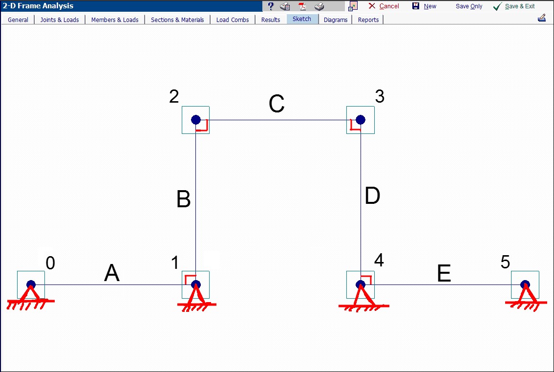
In this model, members A and E are fictitious members that are only there for the purpose of providing partial moment fixity at the bottoms of members B and D. With this concept, it would be possible to experiment with the section and the member length for members A and E to achieve the desired rotational stiffness at joints 1 and 4.
