E-01 (Slender Brick Beam) |
  
|
E-01 (Slender Brick Beam) |
|
Objective
To verify compatible and incompatible brick formulations using regular element shapes
Problem Description
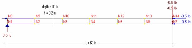
The slender cantilever beam shown below is modeled with 6 rectangular brick elements.
Material properties: E = 1.0e7 psi, ν = 0.3
Section properties: Length = 60 in, height = 0.2 in, thickness t = 0.1 in
Loads: a). unit axial force; b). unit in-plane shear
Finite Element Model
6 brick elements
Model type: 3D Brick
Results
The tip displacements are given by [Ref 1]. Theoretical stresses at the root are also given here for comparison.
Units: displacement – in; stress - psi
Element |
Load type |
ENERCALC 3D |
[Ref 1] |
||
Displacements @ tip |
Stresses @ root |
Displacements @ tip |
Stresses @ root |
||
Compatible |
Axial force |
3.0e-5 |
-50 |
3.0e-5 |
-50 |
In-plane shear |
-0.01007 |
-854.0 |
0.1081 |
-9000 |
|
Incompatible |
Axial force |
3.0e-5 |
-50 |
3.0e-5 |
-50 |
In-plane shear |
-0.1072 |
-8173 |
0.1081 |
-9000 |
|
Comments
The results given by ENERCALC 3D are mixed in comparison with the referenced values.
Compatible and incompatible formulations behave correctly in the axial force loading. For in-plane shear, the incompatible brick formulation yields much better results than the compatible one. In practices, finer meshes should be used to achieve satisfactory results, especially for compatible brick elements.
Reference
[1]. MacNeal & Harder, “A Proposed Standard Set of Problems to Test Finite Element Accuracy”, Finite Elements in Analysis and Design, 1 (1985) 3-20
