A-15 (Multi-DOF Constraints - Cyclically Symmetric Frame) |
  
|
A-15 (Multi-DOF Constraints - Cyclically Symmetric Frame) |
|
Objective
To verify the multi-DOF constraints to enforce cyclic symmetry
Problem Description
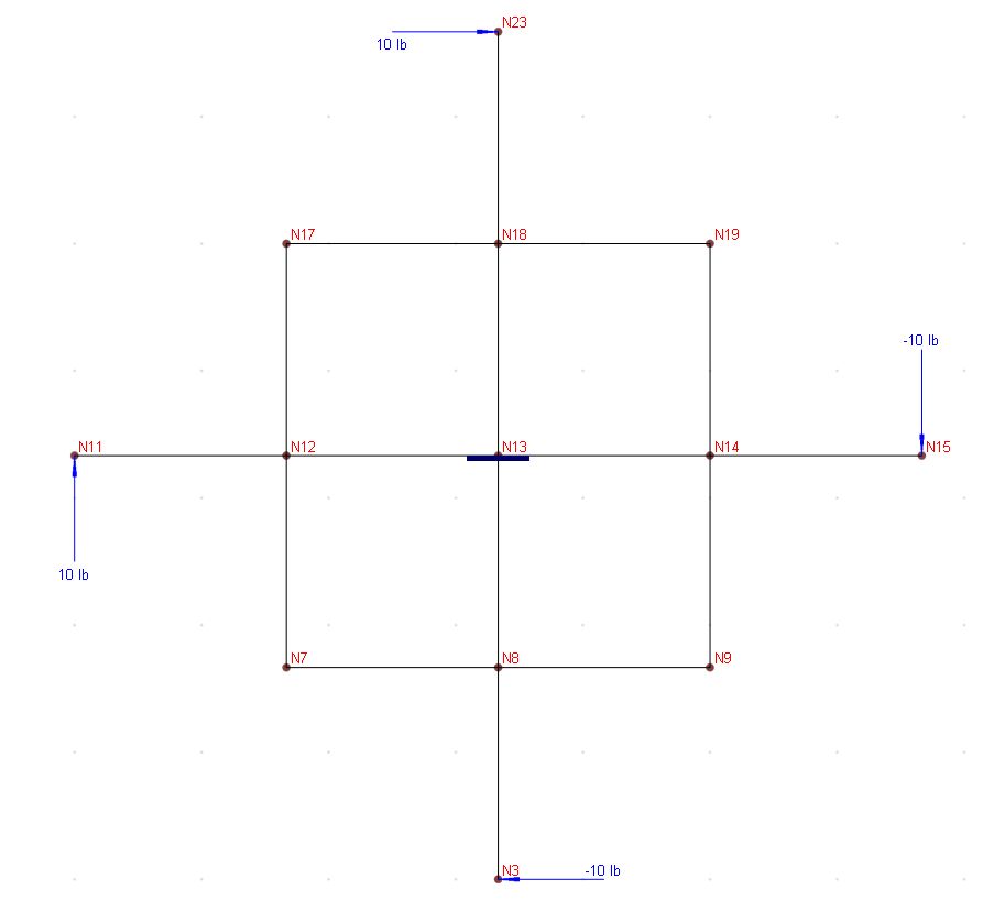
In the frame [Ref 1] below, each of the 16 members is 10 inch long.
Material: E = 1.2e7 psi, ν = 0.15.
Sections: A = 1.0 in2, Iyy = Izz = 8.33e-2 in4
Four cyclic loads: P = 10 lb
Boundary condition: Fixed at the center node (N13)
Finite Element Model
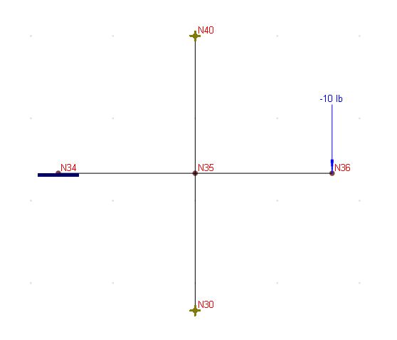
To take advantage of the cyclic symmetry, we are going to model only one quarter of the structure (4-element model) with the following multi-DOF constraints at node 40 and node 30.
X40 = -Y30
Y40 = X30
Oz40 = Oz30
We can use Geometry->Multi-DOF Constraints->Generic Constraints menu to define these three displacement constraints. Alternatively, we can directly enter the constraints in a spreadsheet from Input Data->Multi-DOF Constraints menu.
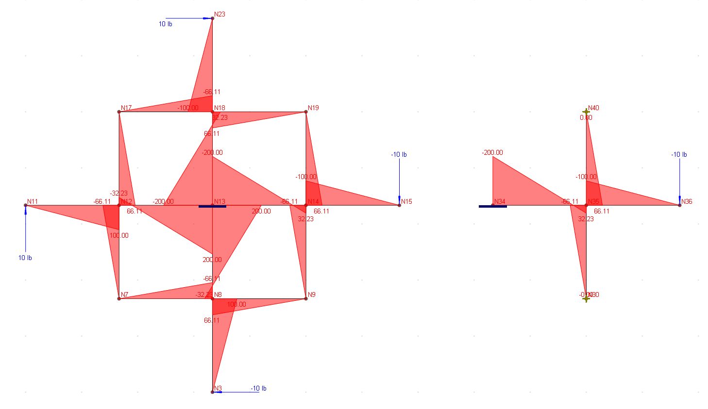
Results
To illustrate, the following shows the identical Mz moment diagrams for both 16-element model and 4-element model.
Reference
[1]. ADINA Verification Manual, ADINA R & D Inc., Example A.40, June 2001
