A-01 (Simple 3d-Truss - Model Type 3D Truss) |
  
|
A-01 (Simple 3d-Truss - Model Type 3D Truss) |
|
Objective
To verify the behavior of the 3d truss element.
Problem Description
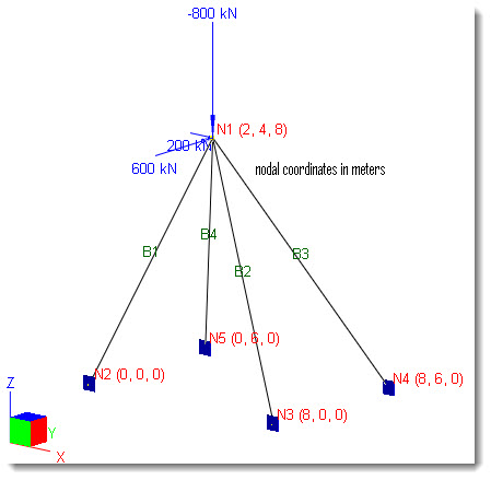
A simple 3d truss is supported and loaded as shown below. Nodal X, Y, and Z coordinates are given in parenthesis.
Material properties: E = 200 KN/mm2, ν = 0.3
Section properties: A12 = 2e4 mm2, A13 = 3e4 mm2, A14 = 4e4 mm2, A15 = 3e4 mm2
All members Iz = 1e10 mm4, Iy = 1e10 mm4 , J = 1e10 mm4
Nodal forces applied at node 1: Px = 200 KN, Py = 600 KN, Pz = -800 KN
Finite Element Model
4 beam elements
Model type: 3D Truss
Results
The displacements and support reactions are given in [Ref 1].
Units: displacement-mm; reaction-KN
|
ENERCALC 3D |
[Ref 1] |
||||
|
X |
Y |
Z |
X |
Y |
Z |
Displacement @ N1 |
0.1779 |
2.722 |
-0.4865 |
0.1783 |
2.722 |
-0.4863 |
Reactions @ N2 |
-76.39 |
-152.78 |
-305.56 |
-76.4 |
-152.8 |
-305.6 |
Reactions @ N3 |
170.83 |
-113.88 |
-227.77 |
170.8 |
-113.8 |
-227.7 |
Reactions @ N4 |
-470.83 |
-156.94 |
627.77 |
-470.7 |
-156.9 |
627.8 |
Reactions @ N5 |
176.39 |
-176.39 |
705.56 |
176.3 |
-176.3 |
705.5 |
Comments
The results given by ENERCALC 3D are very close to the referenced values.
The deflection diagram is shown below for illustration purposes.
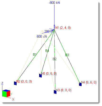
Deflection Diagram
Reference
[1]. McGuire, Gallagher and Ziemian, “Matrix Structural Analysis” 2nd Edition, pp104, John Wiley & Sons, Inc., 2000
