Block & Geogrid Data Tab (for Geogrid Reinforced Walls) |

|

|
Block & Geogrid Data Tab (for Geogrid Reinforced Walls) |
|
|
Block & Geogrid Data Tab (for Geogrid Reinforced Walls)
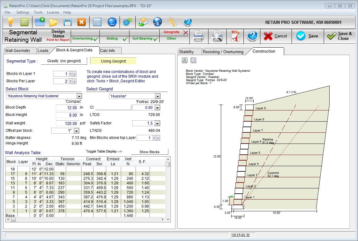
| Segmental Type: | Select either Gravity of Geogrid (this example is with geogrids) |
| Retained height: | Enter the retained height, which is assumed to be the total wall height above the setting base. It should be an even multiple of block heights. |
| Embedment: | Depth below grade to top of setting pad. Usually one block course or 1’-0” |
| Backfill slope: | Select from the drop down menu, which will also display the slope angle. |
| Soil density, exterior (in situ): | Enter the density of the native soil beyond the backfill zone and under the base. |
| Soil density, interior (backfill): | Enter the density of the backfill material (usually granular soil or gravel.). |
| Soil friction angle, Φie, exterior: | Enter the angle of internal friction of in-situ soil. |
| Wall/soil friction angle, δ: | Enter the friction angle at the wall interface (usually 2/3 Φe) |
| Soil friction angle, Φi, interior: | Enter the angles of internal friction of the backfill soil. |
| Surcharge DL, psf: | Enter the dead load surcharge. |
| Surcharge LL, psf: | Enter the live load surcharge – it will not be used to resist overturning or sliding. |
| Seismic kh factor: | Enter seismic acceleration factor. (generally kh = 0.15 maximum – see Methodology) |
| Base width, ft: | Enter the full base width including wall depth. (usually 60% - 70% of retained height). |
Select block
From the drop down menu select the vendor and block you want to use. More vendors will be added as we receive requests. Highlighting a selected block will insert its values into the criteria below.
| Block depth, in: | This will be automatically input based upon block selection. |
| Block height, in: | This will be automatically input based upon block selection. |
| Block weight, psf: | This will be automatically input. Note that the full block depth is assumed to be in-filled and an average density of 120 pcf is used. Note that block weight is in units of psf. Think of looking at an elevation of a constructed wall. It is the weight of one square foot of finished wall. It is calculated by knowing the weight of the solid portion of the block and assuming that any hollow portions are filled with material that weighs 120 pcf. |
| Offset per block, in: | Select this value from the drop down menu – it may be vendor dependent. |
| Batter, degrees: | This angle will be computed and displayed based upon offset and block height entered. |
| Hinge height, ft: | This will be computed and displayed based upon the formula Hh = (block depth) / (tangent of batter angle). |
Select geogrid
From the drop down menu select the geogrid vendor available in your area and the specific geogrid providing the required LTADS which will be displayed below.
| Ci factor: | Enter the geogrid/soil friction factor (usually 0.70 – 0.90) |
| LTDS, lbs/ft: | This displayed value (Long Term Design Strength) will be automatically inserted based upon the vendor/geogrid selection. Or you can enter a custom value. |
| Safety Factor (SF): | Enter desired safety factor to be applied to LTDS. Usually 1.5. |
| LTADS, lbs/ft: | This displayed value (Long Term Allowable Design Strength) is LTDS multiplied by the safety factor selected. |
| Blocks up to layer 1: | Enter the number of blocks from base to first layer. Usually 1 or 2. |
| Blocks between layers: | Enter the number of blocks between successively higher layers. This spacing will be fixed for full height, and is generally one to three blocks. |
| Minimum blocks above top layer: | Enter how many blocks you want as a minimum between top layer and top of wall. Do not exceed Hinge Height. |
Blocks / Layers: (located above the Wall Analysis Table) Clicking between these displays show either all blocks in the Wall Analysis Table, or just the layers. But the count of blocks will be displayed in each case.
Wall Analysis Table:
| Block: | Displays the total number of blocks |
| Layer: | Displays the layer numbers in ascending order from bottom. |
| Ht. above base: | Displays block and layer heights in ft-inches and decimals. |
| Tension, Tu: | Displays the computed unreduced tension at a layer height. |
| Connect, Peak: | Displays the Peak Connection Strength based upon the block and geogrid selected, per the vendor published test-result equation. The displayed value does not exceed the vendor maximum permitted value. The displayed value is reduced by the safety factor specified above. |
| Connect, Serv.: | Displays the ¾” displacement serviceability Connection Strength based upon the block and geogrid selected, per the vendor published test-result equation. The displayed value does not exceed the maximum permitted value. |
| Embed, Le, ft: | The calculated embedment length of the geogrid beyond the failure line as computed by Coulomb method. Factor of safety is applied and one foot is added to the displayed length per NCMA recommendation. |
| Behind Block, ft: | Exact required length of geogrid reinforcing in each layer. The reported length considers the required embedment length (with factor of safety, plus the required one foot) beyond the intersection with the Coulomb failure plane, and it properly accounts for the accumulation of block offsets at each elevation where geogrid occurs. |
| Vert, N: | Accumulated vertical load from blocks above, at indicated height. |
| S.F.: | Indicates safety factor which is the ratio of the lesser of the connect values and LTADS to the Tension, Tu. This value should be at least 1.5, or 1.1 if seismic is included. |
| Base: | Displays total wall weight at bottom of wall. |